0 clearances and dimensions, 1 clearances – Reznor SC Duct Furnace Unit Installation Manual User Manual
Page 5
Form I-SC, P/N 207696 R11, Page 5
Application
Option Shipped Separate Components
Heating -- Gas Control AG7
Thermostat,
P/N 48033
Makeup Air -- Gas
Control Options
(NOTE: If an optional
remote console
is ordered, the
control switch and
temperature selector
may be mounted on the
console.)
AG3
Control Switch,
P/N 29054
AG8
Control Switch,
P/N 29054; Sensor & Mixing Tube,
P/N 48041
AG9
Control Switch,
P/N 29054; Remote Temperature
Selector,
P/N 48042; Sensor & Mixing Tube, P/N 48041
AG15
Control Switch,
P/N 29054; Remote Temperature
Selector,
P/N 115848; Stage Adder Module, P/N
115849; Discharge Air Sensor Holder, P/N 115850;
Discharge Air Sensor Holder Bracket,
P/N 213612
AG39 Remote Temperature Selector, P/N 174849;
Temperature Sensor,
P/N 133228; Mixing Tube,
P/N 90323
Some gas control options will have parts either shipped loose with the heater or
shipped separately. If your unit is equipped with any of the gas control options in the
table below, be sure these parts are available at the job site.
Other shipped-separate
options could include a gas
shutoff valve, a vertical vent
terminal, a thermostat, an
optional control, and/or a
disconnect switch.
Check to see if there are
any field-installed options
that need to be assembled
to the furnace prior to
installation.
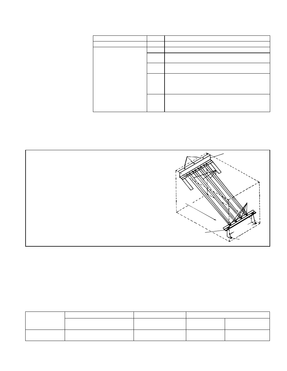
Top Baffle
Support
Screws B
Bottom
Baffle Support
Bracket
s
Air Discharge
Direction of
Airflow
Screw C
Right
Lef
t
Screws A
Screw C
FIGURE 1 - Model SC Heat Exchanger Baffles
3.2.2 Reversing
Airflow by Changing
Direction of Heat
Exchanger Air Baffles
Instructions for Reversing Airflow through the Heat
Exchanger
1.
Remove screws "A". Lift each baffle slightly and slide forward,
removing each completely from the heat exchanger.
2. Remove screws "B" and the rear top baffle support
assembly. Re-position the assembly on the opposite end
of the heat exchanger and attach.
3. Remove screws "C" and the assembled bottom baffle
support and brackets. Plug the holes in the heat
exchanger bottom by re-inserting the screws in the holes.
Position the assembly on the opposite end of the heat
exchanger and attach using field-supplied sheetmetal
screws.
4. Re-install all of the individual baffles by reversing Step 1.
Option Parts
All furnaces are equipped with directional air baffles in the heat exchanger area. Fac-
ing the control compartment of the furnace, the standard direction of airflow is from left
to right. If the installation requires airflow from right to left (when facing the control com-
partment), the position of the directional air baffles may be reversed. Refer to
FIGURE
1 and follow the instructions to reverse the direction of the airflow through the furnace.
4.0 Clearances
and
Dimensions
4.1 Clearances
For safety and convenience, provide clearances as shown in the following table.
Clearance to combustibles is defined as the minimum distance from the heater to a
surface or object that is necessary to ensure that a surface temperature of 90°F above
the surrounding ambient temperature is not exceeded. Minimum clearances are also
listed on the heater rating plate.
Minimum Clearances - inches (mm)
Top
Sides
Bottom
Control Side
Side Opposite
Controls
To
Combustibles
To Non-
Combustibles
6" (152mm)
6" (152mm) plus width of unit
6" (152mm)
6" (152mm)
0" (0mm)