5 pilot ignition systems – Reznor SC Duct Furnace Unit Installation Manual User Manual
Page 31
Form I-SC, P/N 207696 R11, Page 31
Is there 24 volts
between Terminal 2 on #1
Time Delay Relay and
Terminal 7?
Go to
Troubleshooting
Chart for heater.
Is there 24 volts
between Terminal 84 and
Terminal 7?
Is the
damper open?
Is there voltage
between Terminal 88 and
Terminal 7?
Is there voltage
between Terminal 4 on
ignition permissive relay and
Terminal 7?
Replace #1 time delay relay.
Replace ignition
permissive
relay.
Check combustion
damper lower end switch
adjustment. If necessary,
replace end switch.
Is there voltage
between Terminal 87 and
Terminal 7?
Check combustion
damper lower end switch
adjustment. Replace end
switch if necessary.
Place a jumper
across Terminal
86 and Terminal 7.
Did the
damper close?
Replace motor run
time delay relay.
Replace combustion
damper gear motor.
Replace primary
manifold
pressure switch.
YES
NO
YES
NO
YES
NO
YES
NO
YES
NO
NO
YES
YES
NO
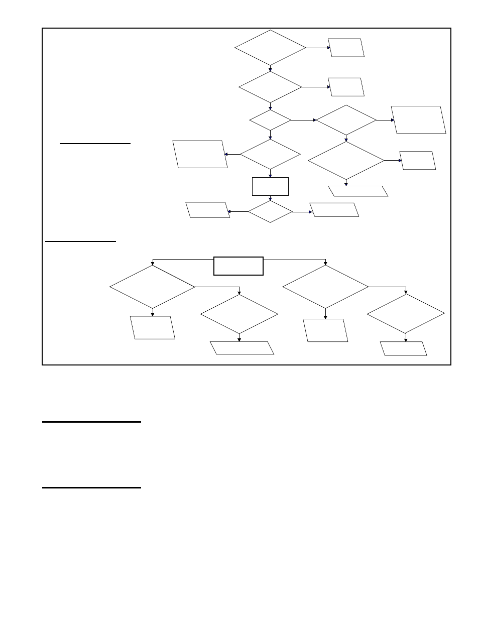
FIGURE 31- Troubleshooting Guide
for Checking Bypass Combustion Air
Damper Safety Circuit on Model SC
with Option AG39 or AG40
General Instructions: For each step,
check to ensure that the wiring is not
defective and that the wiring connections
are secure.
Symptom - Part 1:
Main burners are
inoperative.
Assumes that 24
volts is available
between Terminal 2
and Terminal 7.
Measure manifold
pressure
during burner cycling.
When the
manifold pressure is
BELOW 1.0" w.c., is there a steady
voltage between Terminal 95
and Terminal 7?
Replace secondary
manifold pressure
switch.
While the
burner is cycling, is
there a steady voltage
between Terminal 84 and
Terminal 2?
Replace the primary
manifold pressure switch.
When the
manifold pressure is
ABOVE 1.5" w.c., is there a steady
voltage between Terminal 95
and Terminal 7?
Replace secondary
manifold pressure
switch.
Is there voltage
between Terminal 4 of the
ignition premissive relay and
Terminal 7?
Replace ignition
permissive relay.
YES
NO
YES
NO
YES
NO
Symptom - Part 2: Steady call for heat - burner cycles.
Assumes
that 24 volts
is available
between
Terminals 11
and 7 and
Terminals 2
and 7.
Ignition System - Natural gas units are equipped with a spark ignited intermittent
safety pilot system that shuts off the pilot gas flow between heat cycles. Propane units
(or as an option on natural gas units) require a lockout device that stops the gas flow to
the pilot if the pilot fails to light in 120 seconds. The lockout device has a 1-hour retry
or can be manually reset by interruption of the thermostat circuit. Refer to the wiring
diagram supplied with the unit for pilot system identification and proper wiring. Pilot
with lockout is Option AH3; spark pilot without lockout is Option AH2.
Ignition Controller - As part of the intermittent safety pilot systems, the ignition con-
troller provides the high voltage spark to ignite the pilot gas and also acts as the flame
safety device. After ignition of the pilot gas, the ignition controller electronically senses
the pilot flame. A low voltage DC electrical signal is imposed on the separate metal
probe in the pilot assembly. The metal probe is electrically insulated from ground. The
pilot flame acts as a conduction path to ground completing the DC circuit and proving
pilot flame. Proper operation of the electronic spark ignition system requires a mini-
mum flame signal of .2 microamps as measured by a microampmeter. With pilot flame
proven, the ignition controller energizes the main gas valve.
Pilot - All pilots are vertical, target type with lint-free feature. Pilot flame should be
approximately 1-1/4" in length. Pilot gas pressure should be the same as the supply
line pressure. Pilot gas is supplied through the combination valve; the pilot gas flow
is controlled by an adjustment screw located in the valve body. For maintenance, see
Paragraph 10.2.
CAUTION: Due to
high voltage on
pilot spark wire
and pilot electrode,
do not touch when
energized.
8.5 Pilot Ignition
Systems