4 gas controls, 0 controls (cont'd) – Reznor SC Duct Furnace Unit Installation Manual User Manual
Page 28
Form I-SC, P/N 207696 R11, Page 28
8.4 Gas Controls
8.4.1 Operating Valve
All furnaces are equipped with a 24-volt combination valve which includes the auto-
matic electric on-off valve controlled by the room thermostat, the pressure regulator,
the safety pilot valve, and the manual shutoff valve. The standard gas valve allows for
single-stage control from a single-stage, 24-volt thermostat.
WARNING
The operating valve is the prime safety shutoff. All gas supply lines
must be free of dirt or scale before connecting the unit to ensure
positive closure. See Hazard Levels, page 2.
8.4.2 Optional 2-Stage
Operation - Heating
Only Application
The standard combination control valve is replaced with a two-stage combination gas
control valve providing for low fire or high fire operation controlled by a two-stage
thermostat. First stage (low fire) is factory set (not field adjustable). Both high and low
stages are controlled by a Servo regulator, maintaining constant gas input under wide
variations in gas supply pressure. See instructions packed with the unit for specific gas
valve specifications, wiring, and operating instructions.
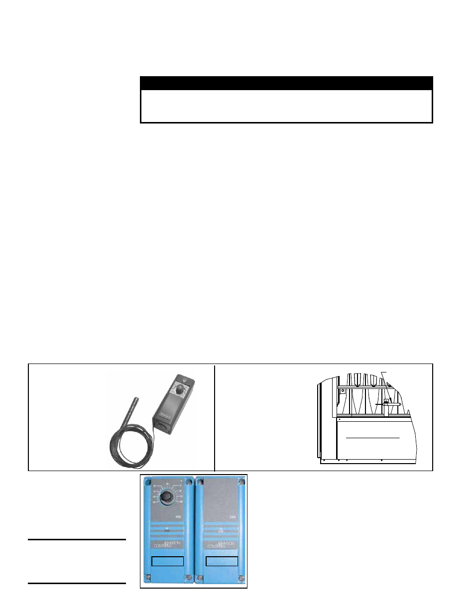
FIGURE 27 - Remote
Temperature Selector
(A) and Stage-Adder
Module (B) in Two-
Stage Makeup Air
Control Option AG15
FIGURE 26B -
Ductstat Bulb
(factory installed)
FIGURE 26A - Ductstat
Control in Option AG3
Factory
set at
70°F
8.4.3 Optional 2-Stage
Operation - Makeup
Air Application
Optional Ductstat with Electronic Remote Set-
point Module (Option AG15) - The sensing probe
is field-wired to a remote temperature selector. The
temperature selector has an operating range to
120°F. The remote modules are shipped separately
for field installation.
Follow the wiring diagram with the unit and the
manufacturer's instructions for wiring and installa-
tion.
There will be one module for selecting temperature
and one-stage adder module as illustrated in
FIG-
URE 27.
(A)
Adjustable range
0-100°F with a fixed
differential of 3°F.
Ductstat Bulb
in Option AG3
Model SC Duct Furnace
Front (Discharge) View
Two-stage makeup air units are equipped with a two-stage gas valve, but instead of
control from a two-stage room thermostat, the outlet air temperature is monitored and
controlled by a two-stage ductstat. When the discharge air temperature drops to the
setpoint, low fire is energized. If low fire cannot satisfy the ductstat setting, high fire is
energized.
Makeup air applications are usually adjusted to discharge an outlet air temperature
between 65°F and 75°F. In all applications, the allowable temperature rise of the fur-
nace in the installation dictates the limits of the ductstat temperature setting.
Depending on the option selection, the sensor is either connected by capillary tubing
to the unit-mounted ductstat (
FIGURES 26A and 26B) or electrically connected to a
remote electronic temperature selector (
FIGURE 27). See Paragraph 6.4.5 for instruc-
tions on locating the sensor in the ductwork.
Optional Ductstat with Capillary Tubing (Option AG3) -- The control illustrated in
FIGURE 26A has an adjustable range from 0° to 100°F with a fixed differential of 3°F.
Due to different CFM settings and outside air temperatures, the average downstream
outlet temperature may not match the ductstat setting exactly. After the installation is
complete, adjust the setpoint of the ductstat to achieve the desired average outlet air
temperature.
(B)
8.0 Controls
(cont'd)
CAUTION: Be sure
heat/cool selector
switch is set at
"Heat" position.