Reznor SC Duct Furnace Unit Installation Manual User Manual
Page 23
Form I-SC, P/N 207696 R11, Page 23
Arlington, VA 22206 (www.acca.org). A manual covering duct sizing in detail may
be purchased directly from them.
Heater
Duct
Access Panel
in Duct
6
(152mm)
10 (254mm)
1
2
3
4
U Channel
Furnace
Duct
U Channel of
Light Gauge Metal
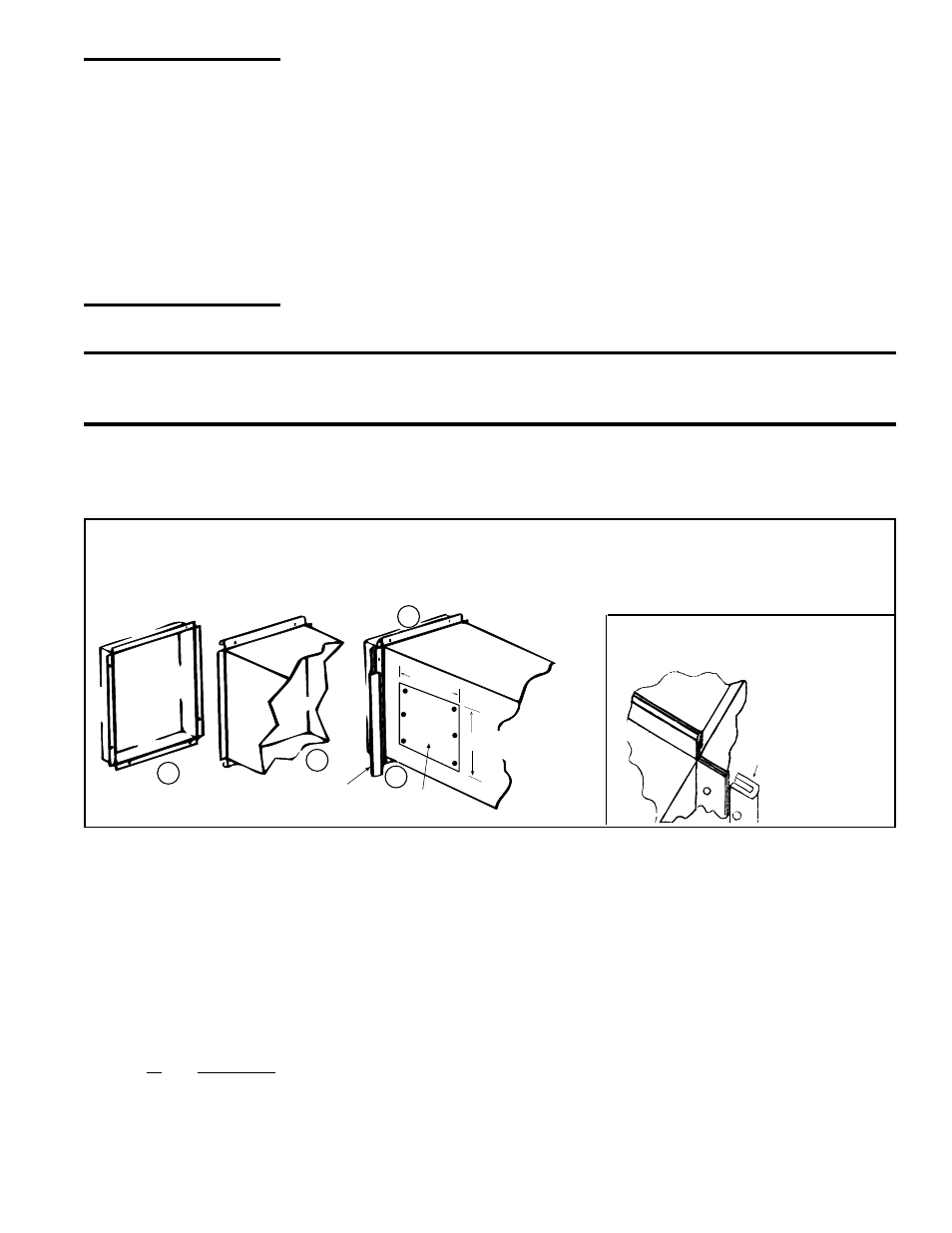
(1) Flanges on the furnace (heat exchanger) turn out as shown. (2) Shape duct connection as shown -- "U" on top
and bottom; "L" on sides. (3) Slide "U" channels over furnace top and bottom flanges making connection. (4) Form
"U" channels to seal sides.
Drill and lock with sheetmetal screws.
FIGURE 22B - Install "U" Channel
on Sides of Duct Connection
FIGURE 22A - Connecting Ductwork to the Furnace
CAUTION: An
external duct system
static pressure not
within the limits
shown on the rating
plate, or improper
motor pulley or belt
adjustment, may
overload the motor.
See Hazard Levels,
page 2.
•
Removable Panels - The ducts should have removable access panels on
both upstream and downstream sides of the furnace. These openings must be
accessible when the furnace is in service and should be a minimum of 6" x 10"
in size so smoke or reflected light may be observed inside the casing to indicate
the presence of leaks in the heat exchanger. The covers for the openings must be
attached in such a manner as to prevent leakage. See
FIGURE 22A.
•
Horizontal Discharge Duct Length - A minimum horizontal duct run of 24" is
recommended before turns or branches are made in the duct system to reduce
losses at the furnace outlet.
•
Supply Air Duct/Furnace Horizontal Connection - The seal between the
furnace and the duct must be mechanical. Duct connection should be made with
"U" type flanges on the top and bottom of the connecting duct. Slide the duct over
the flanges of the heater giving an airtight fit. Provide "U" type channels for the
side flanges to ensure tight joints. Use sheetmetal screws to fasten ducts and "U"
channels to the furnace flange. See
FIGURE 22B.
CAUTION: Joint where supply air duct attaches to the furnace must be sealed securely to
prevent air leakage into the burner rack area. Leakage can cause poor combustion, pilot
problems, shorten heat exchanger life, and poor performance. See Hazard levels, page 2.
•
Return Air Duct/Furnace Connection - All return air ducts should be attached
and sealed to return air flanges to provide airtight connection.
•
Return Air Duct/Grill Size - Make certain that return air ducting or grills have a
free area equal to the return duct size connection.
6.4.5 Discharge Air
Sensor for Makeup
Air Application
Makeup air Option AG3 has a unit mounted ductstat with a capillary sensor that is
factory-installed in the unit discharge (See Paragraph 8.4.3).
Makeup air Options AG15, AG8, AG9, AG39, and AG40 require field installation of the
sensor in the discharge ductwork. Option AG15 uses the box and sensor holder in
FIGURE 23A. Options AG8, AG9, and AG39 include a sensor and mixing tube like the
one illustrated in
FIGURE 23B. Option AG40 requires a field-supplied sensor.
Follow the instructions below to install the sensor in the ductwork.
For control information, see Paragraph 8.4.
Instructions for
Installing Discharge Air
Sensor in the Ductwork
1. Depending on the option, the sensor will be as shown in FIGURE 23A, in FIGURE
23B, or field-supplied for Option AG40. See Paragraph 3.2 for a list of shipped-
separate components by option code.
2. Determine a location in the ductwork to install the sensor.
Select a location a sufficient distance from the outlet to provide a good mixture of
discharge air temperature. According to the latest edition of AMCA Standard 201,
in straight ducts, the air is typically well mixed a minimum of five equivalent duct
diameters from the discharge of the unit with equivalent duct diameter defined