0 controls (cont'd), 4 gas controls (cont'd) – Reznor SC Duct Furnace Unit Installation Manual User Manual
Page 30
Form I-SC, P/N 207696 R11, Page 30
Combustion Air
Pressure Switch
Settings - Options
AG39 and AG40
Sensor Location -
Options AG39
Description of
Operation of Option
AG39
Carryover
Regulator
Modulating
Valve
Single-
Stage Gas
Valve
P rimary Gas
Flow Pressure
Switch
White Label
1.1 w.c.
Gas Flow
Pressure Switch
White Label
1.1 w.c.
8.4.4 Optional
Electronic Modulation
(cont'd)
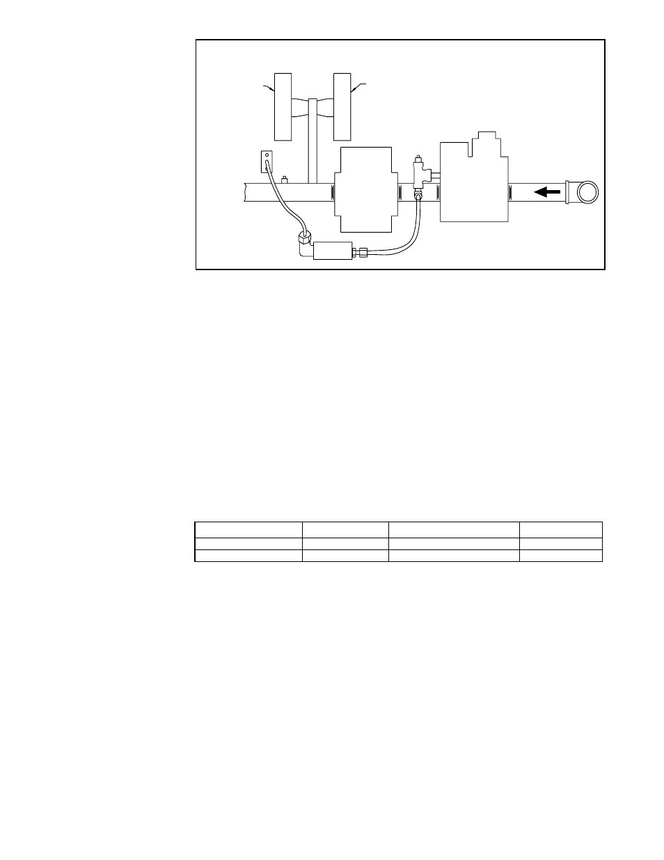
FIGURE 30 - Option AG39 Manifold Arrangement
Note: Arrangement may vary slightly
depending on gas valve; components
are the same.
This uniquely designed modulation system requires combustion air pressure settings
different from the standard system. The approximate settings for the combustion air
proving switch at sea-level operation are:
Sizes with AG39&40
Startup Cold
Equilibrium at Full Rate
Factory Setting
100-225
-1.3"w.c.±0.2
-1.05"w.c.±0.1
-1.0"w.c.±0.02
250-400
-1.2"w.c.±0.2
-0.95"w.c.±0.1
-.70"w.c.±0.05
The duct temperature sensor is shipped loose for field installation. See Paragraph
6.4.5 for determining the sensor location. I
Wiring and Service-
Options AG39 and
AG40
For wiring, consult the wiring diagram attached to the furnace. All wires in the electri-
cal box connecting the modulation controls must have a temperature rating of 150°C.
This is a unique system which includes custom-built components and custom settings.
If service is required, follow the general troubleshooting guide on page 37 and the
special troubleshooting guides in
FIGURE 31.
The gas supply (see pressure requirements in the table above) connects to the single-
stage gas valve. To compensate for additional pressure loss through the modulating
valve, the single-stage gas valve has a custom outlet pressure setting higher than
when it is used on a standard gas manifold. The pilot tubing connects to the pilot port
on the single-stage gas valve. When the valve receives a call for heat from the ampli-
fier and pilot is established, gas flow from the single-stage valve goes to both the mod-
ulating valve and the regulated lighter tube system. When the signal from the amplifier
to the modulating valve requires less-than-high fire operation, the modulating valve
functions to lessen the gas flow to the burner to reduce the input rate to that required to
maintain the desired temperature. When the input rate is reduced enough to decrease
the gas pressure to 1.1" w.c., the primary gas pressure switch in the manifold activates
the gear motor that controls the bypass damper in the venter/combustion air system.
The bypass damper opens diverting some of the incoming air directly into the flue duct,
reducing airflow through the burner. Safety switches monitor the position of the bypass
damper. When the gas pressure increases above 1.1" w.c., the bypass damper closes.
8.0 Controls
(cont'd)
8.4 Gas Controls
(cont'd)
Computer Controlled
Electronic Modulation
between 20-28% and
100% Firing Rate,
Option AG40
- not
available on Size 350;
natural gas only
With this option the furnace is equipped with a Maxitrol signal conditioner (see illustra-
tion in
FIGURE 29B) which accepts an input signal of either 4-20 milliamps or 0-10 volts
from a customer-supplied control device such as a computer. With the dip switches on
the conditioner in the "on" positions, the conditioner accepts a 4-20 milliamp signal. In
the "off" positions, the conditioner accepts a 0-10V signal. The conditioner converts
the signal to the 0 to 20 volt DC current required to control the modulating valve.
The heater functions and is equipped in the same way as described for Option AG39
except that with computer control, the temperatures are selected through the software
and there is no temperature selector or duct sensor.