4 thermostat and control wiring, 0 controls, 1 combustion air proving switch – Reznor SC Duct Furnace Unit Installation Manual User Manual
Page 27: 2 fan control, 3 limit control
Form I-SC, P/N 207696 R11, Page 27
7.4 Thermostat and
Control Wiring
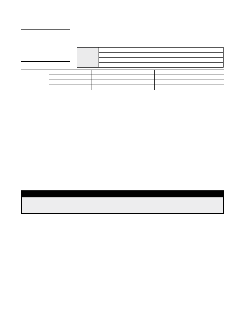
Field Control
Wiring -
Length and
Gauge
Total Wire Length
Distance from Unit to Control Minimum Recommended Wire Gauge
150ft (46M)
75ft (23M)
#18 gauge
250ft (76M)
125ft (38M)
#16 gauge
350ft (107M)
175ft (53M)
#14 gauge
Ampere
Ratings
of 24-Volt
Controls
Fan Control Coil
.12 amps Spark Ignition System
.1 amps
Time Delay Heater .14 amps Maxitrol Gas Control System .51 amps
RBM Relay Coil
.12 amps Honeywell Gas Valve
.5 amps
Contactor Coil
.45 amps White-Rodgers Gas Valve
.6 amps
CAUTION: Control
circuit amps
should be within
the anticipator
amp rating of the
thermostat used.
The heater is equipped with a low voltage (24V) control circuit.
A thermostat is not supplied with the furnace. Use either an optional or a field-provided
low-voltage (24V) thermostat. Install the thermostat according to the manufacturer's
instructions.
If the low voltage thermostat is equipped with a heat anticipator which levels out unit
cycling for optimum temperature control, set the anticipator at 1.0 amps for standard
controls. See chart below for amp ratings of 24-volt controls.
8.1 Combustion Air Proving Switch
The combustion air proving switch ensures that proper combustion airflow is avail-
able. The switch is a single-pole, double-throw switch, which senses pressure caused
by the flow of combustion air from the venter. The switch is designed to close when a
decreasing pressure is sensed in the outlet duct of the gas collection box.
On start-up when the furnace is cold, the sensing pressure is at the most negative
level, and as the furnace and the flue system warm-up, the sensing pressure becomes
less negative. After the system has reached equilibrium (approximately 20 minutes),
the sensing pressure levels off. If a restriction or excessive flue length or turns cause
the sensing pressure to become less than the switch setpoint, the pressure switch will
function to shut off the main burners. The main burners will remain off until the sys-
tem has cooled and/or the flue system resistance is reduced. The table below gives
approximate water column negative pressure readings and switch setpoints for sea
level operating conditions.
Startup Cold
Equilibrium
Factory Setpoint
-1.0" w.c.
-.70" w.c.
-.58 +or- .05" w.c.
NOTE: These settings apply to furnaces that are not equipped with gas modulation Option
AG39 or AG40. For pressure switch settings for units equipped with Option AG39 or AG40, see
Paragraph 8.4.4.
8.0 Controls
DANGER
Safe operation requires proper venting flow. Never bypass the combustion air proving switch or
attempt to operate the unit without the venter running and proper flow in the vent system. Hazardous
condition could result. See Hazard Levels, page 2.
8.2 Fan Control
1. A fan control provides for the following control of the field-supplied blower.
(a) After the gas valve opens, there is a time delay of blower operation to prevent
the discharge of cold air.
(b) Blower operation continues after the thermostat is satisfied as determined by
the fan time delay.
2. To be sure that the blower can continue to operate, the power supply to the
furnace
MUST NOT be interrupted except when servicing the unit.
3. If the customer wants the furnace off at night, the gas valve circuit SHOULD
BE OPENED by a single pole switch wired in series with the thermostat. Some
thermostats are provided with this feature. Multiple units controlled from a single
thermostat are shut off in the same manner. For proper operation, be sure the fan
control wiring is observed.
Service NOTES: To
replace the fan control on
units manufactured prior to
11/04, a replacement kit is
required. Order P/N 209184.
Prior to 10/03, the fan con-
trol was optional. Check
the wiring diagram on the
furnace.
8.3 Limit Control
All models are equipped with an automatic, non-adjustable reset limit control that acts
to interrupt the electric supply to the redundant main operating valve in case of motor
failure or lack of airflow due to restrictions at the inlet or outlet.