2 duct furnace blower connection, Warning, Figure 19a - straight through air – Reznor SC Duct Furnace Unit Installation Manual User Manual
Page 21: Figure 19b - with elbows up or down, Figure 19c - with elbows left or right
Form I-SC, P/N 207696 R11, Page 21
6.4.2 Duct Furnace
Blower Connection
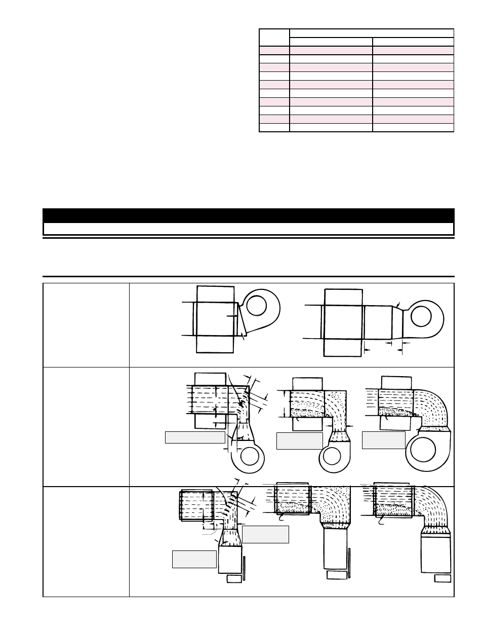
Proper air arrangement of blower and duct furnace with respect to angle of approach
of the duct connection and the arrangement of the discharge opening of the blower are
shown in
FIGURE 19. Blowers should be bottom horizontal discharge when coupled
to the duct furnace. When a top horizontal discharge blower is connected to the duct
furnace, be sure that sufficient length of duct is provided to permit an even flow of air
at the furnace. Or, insert baffles between the blower and the heater to assure an even
flow of air across the heat exchanger.
Direct
Coupling
Slanted Transition
Suggested blower connections for straight through airflow. Use
either method for good air coverage and efficient operation.
15°
6 (152mm)
Remote
24
(610mm)
minimum
Turning Vanes
3
(76mm)
3(76mm)
3(76mm)
6 (152mm)
6 (152mm)
X
15°
Y
No air
X
No air
Z
NOTE: X should
never be less than 1/2 Y
NOTE: X should
never be less
than 1/2 Y
NOTE: Angle Z
should never be
more than 15°
Turning Vanes
3
(76mm)
3(76mm)
3(76mm)
6 (152mm)
6 (152mm)
Z
NOTE: Angle Z
should never be
more than 15°
X
15°
No air
No air
GOOD
GOOD
POOR
POOR
POOR
POOR
Y
Y
NOTE: X should
never be less than
1/2 Y
FIGURE 19A -
Straight
Through Air
vanes should be used in elbows or turns in the air inlet
to ensure proper air distribution (See Paragraph 6.4.2).
If it is determined that the blower CFM is greater than
allowed or desirable, see Paragraph 6.4.3 for instruc-
tions on determining the correct size of bypass duct
required.
Or, if a higher CFM is required through the furnace
within the limits in the chart on the right, install the high
CFM conversion kit, P/N 263309, that was shipped with
the unit.
Model
SC Size
High Air Throughput (CFM) with Kit, P/N 263309
MAXIMUM
MINIMUM
100
3700
980
125
4630
1230
150
5555
1480
175
6480
1725
200
7405
1975
225
8330
2220
250
9255
2465
300
11110
2960
350
12900
3455
400
14815
3950
FIGURE 19B -
With Elbows
Up or Down
WARNING
The furnace must be installed on the positive pressure side of the air-circulating blower.
CAUTION: Abrupt angle approaches such as shown in FIGURES 19B and 19C can be
detrimental to unit life. Be certain that ample air is directed at the base of the tube section
by using turning vanes as shown. See Hazard Levels, page 2.
Direct
Coupling
Slanted Transition
Suggested blower connections for straight through airflow. Use
either method for good air coverage and efficient operation.
15°
6 (152mm)
Remote
24
(610mm)
minimum
Turning Vanes
3
(76mm)
3(76mm)
3(76mm)
6 (152mm)
6 (152mm)
X
15°
Y
No air
X
No air
Z
NOTE: X should
never be less than 1/2 Y
NOTE: X should
never be less
than 1/2 Y
NOTE: Angle Z
should never be
more than 15°
Turning Vanes
3
(76mm)
3(76mm)
3(76mm)
6 (152mm)
6 (152mm)
Z
NOTE: Angle Z
should never be
more than 15°
X
15°
No air
No air
GOOD
GOOD
POOR
POOR
POOR
POOR
Y
Y
NOTE: X should
never be less than
1/2 Y
FIGURE 19C -
With Elbows
Left or Right