Reznor SC Duct Furnace Unit Installation Manual User Manual
Page 11
Form I-SC, P/N 207696 R11, Page 11
4) Joints and Sealing
Provide pipes as specified in
Requirement No. 1, pages 9-10, and seal joints as fol-
lows:
•
If using Category III vent pipe run, follow the pipe manufacturer’s instructions for
joining and sealing Category III vent pipe sections.
•
If using single-wall vent pipe run, secure slip-fit pipe connections using
sheetmetal screws or rivets. Seal all joints with aluminum tape or silicone sealant.
•
To seal joints in the single-wall combustion air pipe, secure slip fit pipe
connections using sheetmetal screws or rivets. Seal all joints with aluminum tape
or silicone sealant.
•
To seal joint in the terminal section of double-wall vent pipe (allowed
ONLY ABOVE the concentric pipes on a VERTICAL vent, follow the pipe
manufacturer’s instructions for joining and sealing double-wall vent pipe sections.
•
When joining the terminal section of double-wall vent pipe to the vent cap,
follow the illustrated step-by-step instructions in
FIGURE 6.
When joining the terminal section of double-wall vent pipe to a single-wall
or Category III vent pipe run, follow the illustrated step-by-step instructions in
FIGURE 7.
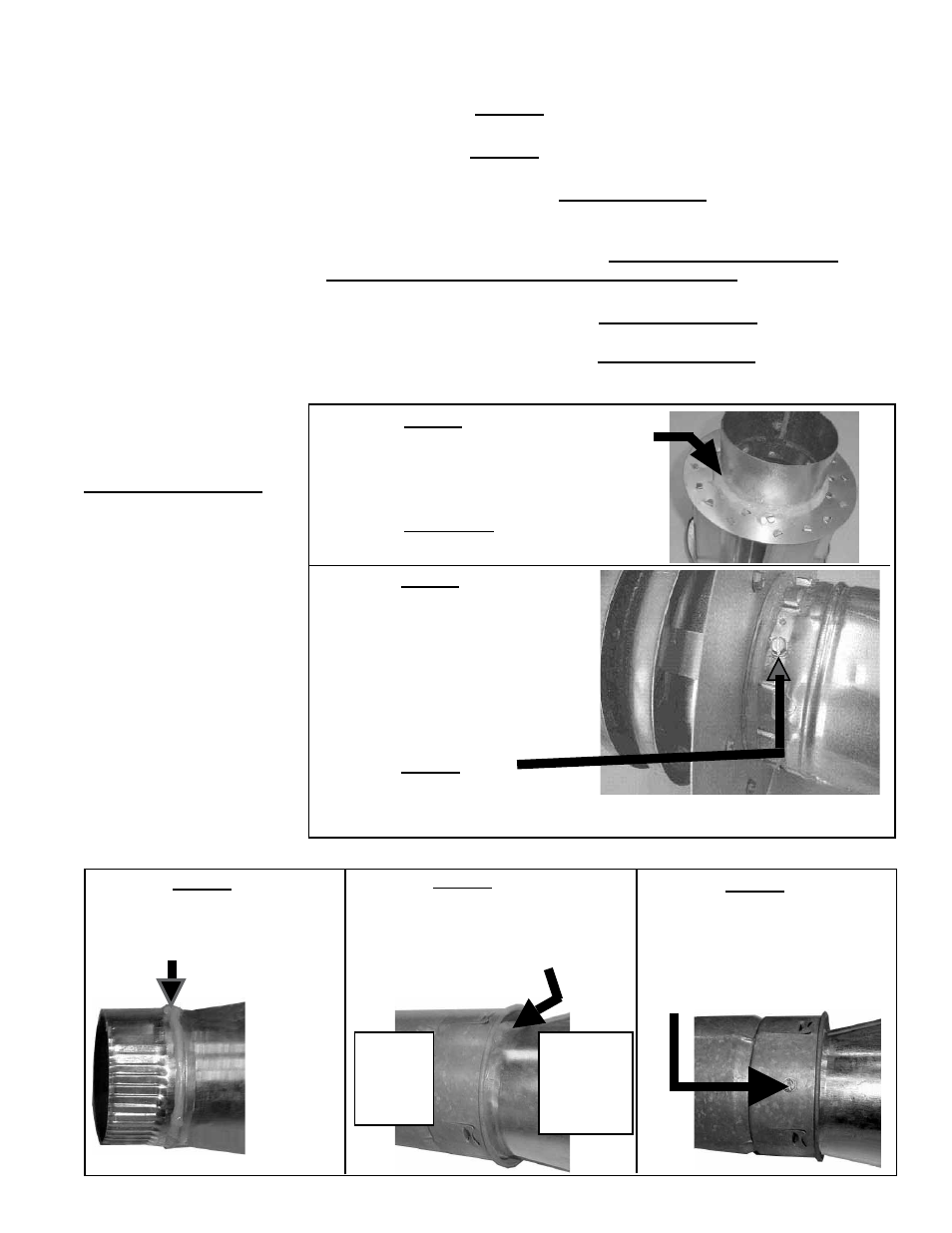
FIGURE 6 - Follow
STEPS to join Double-
Wall (Type B) Pipe and
the Vent Terminal Cap
(horizontal or vertical)
Figure 6 - STEP 1
Place a continual 3/8” bead of silicone sealant
around the circumference of the vent cap col-
lar. This will prevent any water inside the vent
cap from running down the double-wall pipe.
Do STEP 2 immediately following STEP 1.
Figure 6 - STEP 2
Insert the collar on the vent cap inside
the inner wall of the double-wall pipe.
Insert as far as possible. Add addi-
tional silicone sealant to fully close
any gaps between the vent cap and
the double wall pipe. This is neces-
sary to prevent water from entering
the double wall pipe.
Secure the vent cap to the double-wall
pipe by drilling and inserting a 3/4” long sheetmetal screw into the vent cap collar.
Do not overtighten screw.
Figure 6 - STEP 3
(NOTE: Pipes and vent
caps may not look exactly
as shown in the illustrations.
Instructions apply to both
horizontal and vertical vent
kits.)
FIGURE 7 - Follow
STEPS to join the
Double-Wall (Type B)
Pipe to the Taper-type
Reducer that Joins it
to the Single-Wall or
Category III Vent Run
Figure 7 - STEP 1
On the taper-type reducer, place a
continual 1/4” bead of silicone seal-
ant around the circumference.
Figure 7 - STEP 2
Insert the collar of the reducer into the
inner pipe of the double-wall pipe until
the bead of sealant contacts the inner
pipe creating a sealed joint.
Figure 7 - STEP 3
Spaced equally around the double-
wall pipe, drill three small holes
below the sealant ring. Insert 3/4
inch long sheetmetal screws to
secure the joint. Do not overtighten
screws.
Make this connection a maximum of 6" (152mm) from the concentric adapter box.
6" to 5"
or 7" to
5" Taper-
Type
Reducer
Do STEP 2
immediately
following
STEP 1.
5" I.D.
Double-
Wall
Pipe