Reznor SC Duct Furnace Unit Installation Manual User Manual
Page 15
Form I-SC, P/N 207696 R11, Page 15
2. Install the Vent Pipe and Combustion Air Pipe Runs - Use the type of pipe speci-
fied in Requirement No. 1, pages 9-10. Comply with requirements in Requirement No.
2, page 10, when attaching pipes to the heater.
Seal all joints. Due to the high temperature,
do not enclose the exhaust pipe or place
pipe closer than 6" (152 mm) to combustible material. Extend the runs close to the
wall location selected in Step 1. Support pipes as required in Requirement No. 5, page
12.
3. Prepare a hole through the outside wall for the 8" (203mm) diameter combus-
tion air pipe. Outside wall construction thickness should be between 1" (25mm) mini-
mum and 48" (1143mm) maximum. The larger diameter combustion air pipe serves
as clearance for the vent pipe on non-combustible construction. A thimble may be
required depending on wall construction and/or local codes.
4. Prepare the Concentric Adapter Box
a) Attach the brackets to the box. Follow the instructions in FIGURE 11.
WARNING
All vent terminals must be positioned or located away from fresh air intakes, doors and windows
to preclude combustion products from entering occupied space. Failure to comply could result in
severe personal injury or death and/or property damage.
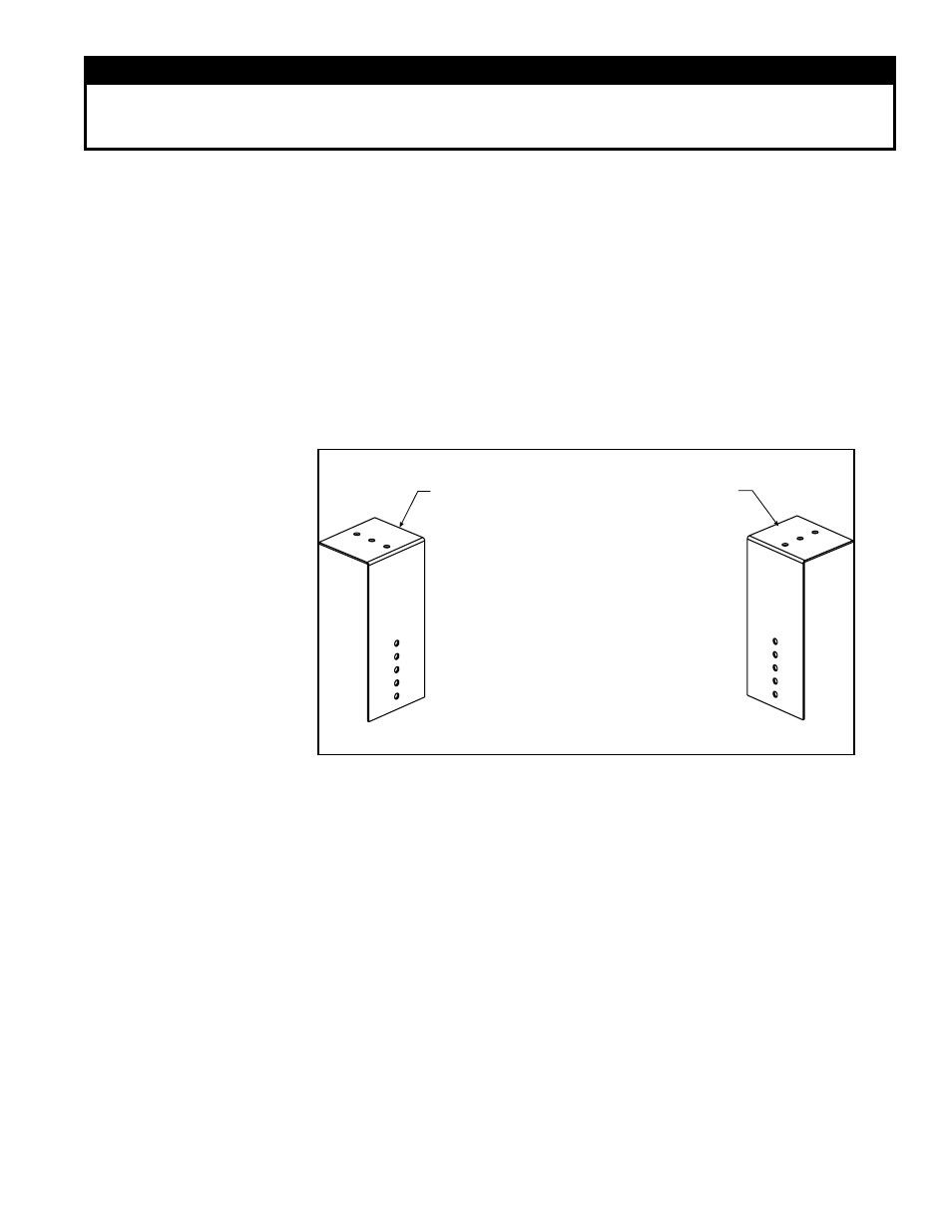
FIGURE 11 - Brackets
for Attaching the
Concentric Adapter Box
to the Wall
1) Attach the Brackets to the Box - The 6
(152mm) portion of each bracket is
designed with five 7/32 diameter holes
so that attachment to the box can be
adjusted.
If the wall is combustible, position brackets to
allow for a 2 (51mm) clearance between the
box and thewall.
Adjust bracket attachment to allow for the slight
downward pitch of the terminal vent pipe.
After careful positioning, use sheetmetal screws
to attach the brackets. NOTE: If any holes are
made in the box in error, they must be sealed.
2) Attach the Box to the Wall (Step 5)
When the box is attached to the wall in Step 5,
use the 2-1/2 (64mm) portion of the brackets.
To adjust to construction each bracket has
three 7/32 diameter holes.
b) Attach the outside portion of the combustion air pipe to the box. Determine
the length by measuring the bracket length from box to wall, plus the wall thickness,
plus 2" (51 mm). (The inlet air pipe should extend beyond the outside wall
approximately 2" (51mm).)
Attach the inlet air pipe to the collar of the concentric adapter with sheetmetal screws
and seal.
5. Attach the concentric adapter box to the wall. Insert the combustion air pipe
through the wall.
Attach the brackets (FIGURE 11) to the wall. On the outside, caulk or
flash the inlet air pipe. Flashing is field-supplied.
6. Position the inlet guard over the end of the combustion air pipe. See FIGURE 12,
page 16. Attach the guard to the inlet air pipe with the four 1/2" long screws provided.
7. Determine length and install the double-wall terminal vent pipe.
a) Determine length of pipe. The length of the vent pipe is determined by the instal-
lation within the maximum and minimum requirements. See
FIGURE 12, to determine
lengths of each segment and calculate the total length required. The vent pipe extend-
ing through the box and the inlet air pipe
must be one piece of double-wall vent pipe
without joints. The transition to the single-wall or Category III vent pipe run, must be
a maximum of 6” (152mm) from the heater side of the box.
b) Install double-wall terminal vent pipe. Being sure the vent pipe is in the proper
flow direction, slide the end through the box. Position the vent pipe so that it will extend