Vertical vent instructions – Reznor SC Duct Furnace Unit Installation Manual User Manual
Page 17
Form I-SC, P/N 207696 R11, Page 17
10. Attach the indoor combustion air pipe. If using 6" pipes, attach the single-wall
combustion air pipe run to the collar on the concentric adapter box with sheetmetal
screws. If using 7” pipe on Sizes 200-400, install a taper type enlarger as illustrated In
FIGURE 9B, page 13.
Seal joints with tape or sealant.
Installation of the horizontal vent and combustion air system on your separated-com-
bustion unit is complete.
Verify compliance with all venting installation require-
ments, pages 9-13, and illustrated in FIGURE 12.
FIGURE 13 - Parts
in the Vertical Vent
Terminal/Combustion
Air Package (Option
CC2)
Components Required
- Factory and Field
VERTICAL VENT
INSTRUCTIONS
Field-supplied
installation
requirements:
• Vent pipes - see requirements, page 10.
• Combustion air pipes - see requirements, page 10.
• Taper-type pipe diameter reducers and/or increasers as required
• Thimble (a thimble is not required if wall is of non-combustible construction)
• Flashing
• Sheetmetal screws, tape, and sealant as required
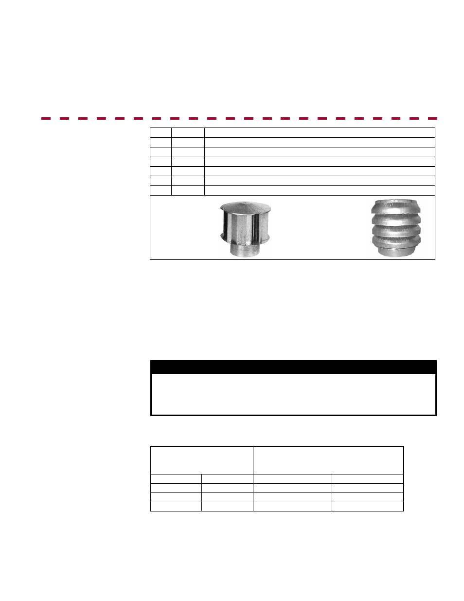
Exhaust
(Vent)
Terminal,
P/N 110052
Combustion
Air Inlet,
P/N 53330
Qty
P/N Description
1
205896 Complete Vertical Vent Kit (Same as Option CC2)
1
205885 Concentric Adapter Box Assembly (See
FIGURE 8, page 12)
1
110052 Exhaust (Vent) Terminal (illustrated below)
1
53330 Combustion Air (illustrated below)
2
207232 Brackets for attaching Concentric Adapter Box (
FIGURE 14, pg 18)
1
53335 Tube of High Temperature Silicone Sealant
Installation Instructions
for Vertical Vent/
Combustion Air Kit
Option CC2
1. Determine the location of the vent terminal.
Select a location away from fresh air intakes, allowing space for the concentric adapter
box inside. Vent terminal must be located from adjacent buildings as shown in
FIGURE
18, page 20.
If more than one vertical concentric vent/combustion air terminal (Option CC2) is being
installed, the minimum spacing between vent centerlines is determined by the mini-
mum outdoor design temperature (most extreme outdoor condition at the site).
Minimum Outdoor Design
Temperature
Minimum Spacing between Centerlines
of Vent Pipes in Vertical Combustion
Air/Vent Terminals (Option CC2)
°F
°C
inches
mm
31 or warmer 0 or warmer
36
914
-10 to 30
-23 to -1
60
1524
less than -10 less than -23
84
2134
2. Install the Vent Pipe and Combustion Air Pipe Run - Use the type of pipe speci-
fied (Requirement No. 1, pages 9-10), and comply with the attachment requirements in
Requirement No. 2, page 10. Length must comply with Requirement No. 3, page 10.
Seal all joints. Due to the high temperature,
do not enclose the exhaust pipe or place
pipe closer than 6" (152 mm) to combustible material. Provide supports for the pipes.
Extend the runs to close to the roof at the location selected in Step 1 above.
WARNING
All vent terminals must be positioned or located away from fresh air
intakes, doors and windows to preclude combustion products from
entering occupied space. Failure to comply could result in severe
personal injury or death and/or property damage.