Reznor SC Duct Furnace Unit Installation Manual User Manual
Page 19
Form I-SC, P/N 207696 R11, Page 19
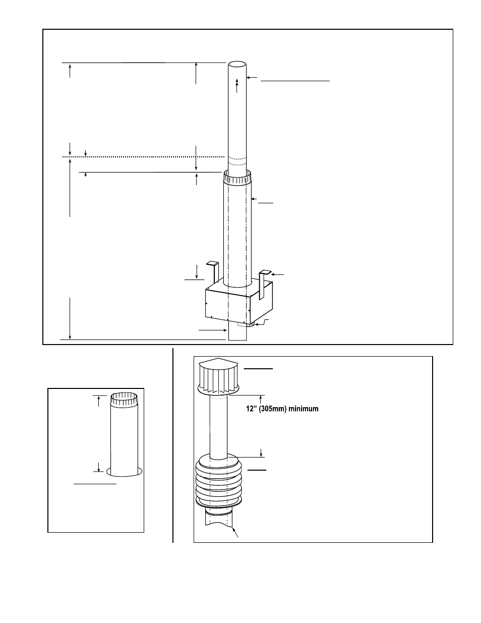
FIGURE 15 - Assemble Concentric Adapter Box, Outdoor Combustion Air Pipe, and Double-Wall
Vent Pipe
Concentric
Adapter Box
Mounting Brackets
X = length of
combustion air pipe required
through and above the roof.
Height from box to top of inlet air
pipe must not exceed 48 (1219mm).
Minimum height above the roof is
18 (457mm) and must be higher
than anticipated snow depth.
First, attach Combustion Air Pipe and install the
Concentric Box
1) Determine length (X) of pipe (see requirements
on the left).
2) Attach the pipe to the collar on the box.
3) Attach the brackets to the roof.
V
ent Flow
22 (559mm) minimum
Cold Climate NOTE:
In geographic areas
where the design ambient
is -10°For lower, this
minimum height
is 34 (864mm).
Collar for Indoor Portion of
the Combustion Air Pipe
Double-Wall Vent Pipe -
Extend length of double-wall
vent pipe a maximum of 6
(152mm) below the box.
After box is installed, install Concentric Vent Pipe -
One piece of continuous double-wall pipe must extend
from a minimum of 3 (76mm) above the outer com-
bustion air pipe to a maximum of 6 (152mm) below
the box. (NOTE: Vent pipe does not attach to the box;
it must be supported.)
1) Calculate height (see requirements on the left).
2) Be sure vent flow marking on pipe is in the right
direction.
3) Slide pipe through the box and the outer inlet air pipe.
4) Attach to vent run no more than 6 (152mm) from the
adapter box. See instructions on page 12.
Vent pipe
extending
through the
box and the
combustion
air pipe MUST
be one continuous
piece of double-
wall vent pipe.
A second section
of double-wall pipe
is permitted, joining
the long continuous
piece of vent pipe a
minimum of 3 (76mm)
above the top of the
combustion air pipe.
3 (76mm)
minimum
FIGURE 17 - Install Combustion Air Inlet and Vent Terminal
FIGURE 16 - Slide attached
Combustion Air Pipe up
through the Roof
Outside View with
concentric adapter
box attached to under-
side of roof.
Install field-supplied
flashing at roof opening.
Snow Clearance
18 (457mm)
minimum
(NOTE: Maximum
from concentric
adapter box is
48 (1219mm)
9. Attach the indoor combustion air pipe. Use sheetmetal screws to attach the sin-
gle-wall combustion air pipe run to the collar on the concentric adapter box. Seal with
tape or sealant. If using 7” pipe on Sizes 200-400, install a taper type enlarger as illus-
trated in
FIGURE 9B, page 13.
SECOND, Install the Exhaust (Vent) Terminal.
Follow the instructions in FIGURE 2, page 3.
FIRST, Install Combustion Air Inlet.
1) Slide the combustion air inlet over the vent pipe.
2) Fasten bottom of inlet to the combustion air pipe
with sheetmetal screws. Be sure not to penetrate
the vent pipe.
3) At the top, completely seal the space between the
vent pipe and the air inlet with silicone.
Double-wall V
ent Pipe
Cold Climate NOTE: In geographic
areas where the design ambient is
-10°F or lower, this minimum height
is 24” (610 mm)
Single-wall Combustion Air Pipe