0 electrical supply and connections, 1 general, 2 supply voltage and wiring – Reznor SC Duct Furnace Unit Installation Manual User Manual
Page 24: 0 mechanical (cont'd), 4 duct furnace airflow (cont'd)
Form I-SC, P/N 207696 R11, Page 24
7.0 Electrical
Supply and
Connections
7.1 General
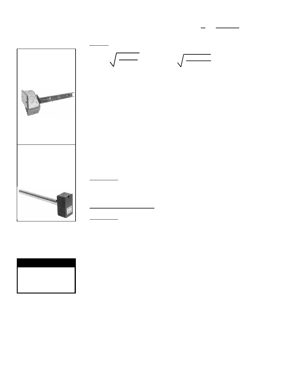
FIGURE 23A -
Discharge Air Sensor
Holder, P/N 115850,
used in Makeup Air
Option AG15
Secure sensor in clip.
Position holder so that it
shields sensor from direct
airflow.
FIGURE 23B - A
Discharge Air Sensor
and Mixing Tube are
used in Electronic
Modulation Options
AG8, AG9, and AG39
6.0 Mechanical
(cont'd)
6.4 Duct Furnace
Airflow (cont'd)
as equal to the square root of 4AB/3.14. "A" and "B" are the duct cross-sectional
dimensions.
Example:
Supply ductwork cross-sectional dimension is
24" x 12" (610mm x 305mm).
5 x
4 x 12 x 24
3.14
= 96"
5 x
4 x 305 x 610
3.14
= 2435mm
Solution: Locate the sensor a minimum of 96" (2435mm)
from the outlet of the unit.
NOTE: If the length of the discharge duct is less than 8 ft (2.4M), a mixing vane is
recommended for mixing the discharge air.
Do not mount the sensor in the ductwork after a split in the supply as that will
cause loss of control in the duct that does not house the sensor.
3. The position of the sensor holder or mixing tube is important. The holder in
FIGURE 23A will extend 9-3/16” (233mm) into the ductwork. The mixing tube in
FIGURE 23B is 12" (305mm) long.
In horizontal ductwork, locate the sensor assembly in the top, middle of the duct
with the sensor probe extending vertically down into the center of the airstream.
In vertical ductwork, locate the sensor assembly in the middle of the side of the
duct that corresponds with the top middle of the discharge outlet.
Turn the holder so that the element will be shielded from direct airflow and will
sense the air temperature as it flows through the holes in the holder.
At the selected location in the ductwork, mark the diamond-shaped hole
[approximately 1” x 1” (25mm x 25mm)] required for the sensor holder or the round
hole needed for the mixing tube. Cut the hole no larger than required.
4. Option AG15 - Push the element into the clip in the holder. Determine where the
sensor wire should enter the box and remove the knockout. Slide the holder into
the ductwork. Using four field-supplied No. 6 sheetmetal screws, attach the box
portion of the holder to the ductwork. Attach a field-supplied cable connector to the
box, connect the sensor wire, and attach the box cover.
Options AG8, AG9, and AG39 - Slide the mixing tube into the ductwork and
attach the sensor. Connect the wires as shown on the wiring diagram.
Option AG40 - Follow the instructions provided with the field-supplied sensor.
Refer to the wiring diagram with the unit and the field-supplied sensor to connect
the wires.
6.4.5 Discharge Air Sensor for Makeup Air Application (cont'd)
Instructions for Installing Discharge Air Sensor in the Ductwork (cont'd)
WARNING
If you turn off the
power supply, turn off
the gas. See Hazard
Levels, page 2.
All electrical wiring and connections including electrical grounding must be made in
accordance with the National Electric Code ANSI/NFPA No. 70 (latest edition) or, in
Canada, the Canadian Electrical Code, Part I-C.S.A. Standard C22.l. Check any local
ordinances or gas company requirements that apply.
7.2 Supply Voltage and Wiring
Check the rating plate on the heater for the supply voltage and the current require-
ments. A separate line voltage supply with fused disconnect switch should be run
directly from the main electrical panel to the unit, making connections in the junction
box. Refer to
FIGURE 2, Paragraph 4.2. Seal all electrical entrance openings with
field-supplied bushings.
A disconnect switch is available as optional equipment or may be supplied locally.
When installing the disconnect switch, be careful that the conduit and switch housing
are clear of all service panels. Allow at least four feet (1.2M) of service room between
the disconnect switch and any removable service panels. When providing or replacing
fuses in a fusible disconnect switch, use dual element time delay fuses and size 1.25
times the maximum total input amps.
See typical wiring diagram in
FIGURE 24 or 25; a specific wiring diagram can be found
in the heater junction box. See separate instruction sheets for any optional equipment
provided. Electrical options are identified on the wiring diagram on the heater.