0 mechanical (cont'd), 3 venting and combustion air (cont'd), Vertical vent instructions (cont'd) – Reznor SC Duct Furnace Unit Installation Manual User Manual
Page 18
Form I-SC, P/N 207696 R11, Page 18
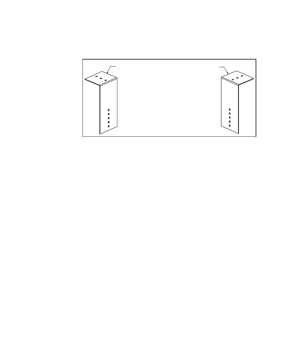
FIGURE 14 - Brackets
for Attaching the
Concentric Adapter Box
to the Roof
4. Prepare the Concentric Adapter Box
a) Attach the brackets to the box. Follow the instructions in FIGURE 14.
1) Attach the Brackets to the Box - The 6 (152mm)
portion of each bracket is designed with five
7/32 diameter holes so that attachment to the
box can be adjusted.
If the roof is combustible, position brackets to allow for
a 2 (51mm) clearance between the box and the roof.
After careful positioning, use sheetmetal screws to
attach the brackets. NOTE: If any holes are made in
the box in error, they must be sealed.
2) Attach the Box to the Roof (Step 5)
When the box is attached to the roof in Step 5, use the
2-1/2 (64mm) portion of the brackets. To adjust to
construction each bracket has three 7/32 diameter holes.
5. Attach the concentric adapter box to the roof. On the inside, insert the combus-
tion air pipe up through the opening and attach brackets to the roof. (See
FIGURES
15 and 16.) On the outside, flash the combustion air pipe to the roof. Flashing is field
supplied
.
6. Determine the length and install the double-wall vent pipe.
a) Determine the length. See FIGURE 15 to determine the required length of the vent
pipe. The vent pipe extending through the box and the inlet air pipe
must be one piece
of double-wall vent pipe without joints.
Determine the minimum length by adding the requirements. Starting at the bottom, the
maximum the vent pipe can extend below the box is 6” (152mm);
plus 6” (152mm)
through the box;
plus length of bracket extending above the box; plus the width of the
roof;
plus the height of the outside combustion air pipe above the roof; plus a mini-
mum of 3” (76mm) beyond the top of the inlet air pipe. Total is the minimum length of
the vent pipe section. If the actual piece of vent pipe is longer, extend it further above
the combustion air pipe. Do not extend it more than 6” (152mm) below the box.
b) Install the pipe. Being sure the pipe is in the proper flow direction, slide the end into
the box and out through the combustion air pipe. Position the vent pipe so that the end
is no more than 6” (152mm) below the box. The upper end should extend at least 3”
(76mm) above the combustion air pipe.
NOTE: The double-wall vent pipe does not
attach to the box. The installer must provide support.
Follow the instructions in
FIGURE 7, page 11 for connecting the double-wall pipe to the
single-wall pipe or Category III vent pipe run. A taper-type reducer is required.
Seal the circumference of the pipe and the opening of the box with silicone sealant.
Seal the area around the pipe completely.
7. On the outside, slide the combustion air inlet over the vent pipe and fasten the
collar to the combustion air pipe with sheetmetal screws. See
FIGURE 17. Seal the
opening at the top between the vent pipe and the combustion air inlet with silicone
sealant to prevent water leakage.
8. Attach the exhaust (vent) cap. See FIGURE 17 and follow the illustrated instruc-
tions in
FIGURE 6, page 11.
b) Attach the outside portion of the combustion air pipe to the box. Determine
the length of the combustion air pipe so that dimension ”X” in
FIGURE 15 is equal to
the bracket length, plus the roof thickness, plus anticipated snow depth, but does not
exceed 48“ (1219mm) or have less than 18” (457mm) of pipe above the roof. Attach
the inlet air pipe to the collar of the concentric adapter box with sheetmetal screws.
6.3 Venting and
Combustion Air
(cont'd)
6.0 Mechanical
(cont'd)
VERTICAL VENT INSTRUCTIONS (cont'd)
3. Prepare a hole through the roof for the 8" (203mm) diameter combustion air
pipe. A thimble may or may not be required depending on building construction and/or
local codes. The larger diameter combustion air pipe serves as clearance for the vent
pipe on non-combustible construction.