0 mechanical (cont'd), 4 duct furnace airflow (cont'd) – Reznor SC Duct Furnace Unit Installation Manual User Manual
Page 22
Form I-SC, P/N 207696 R11, Page 22
Requirements and
Suggestions for
Connecting and
Installing Ducts
18
(457)
G
3/4 (19)
3/4 (19)
Size
G
100
12-1/2" (318mm)
125
15-1/4" (387mm)
150, 175
20-3/4" (527mm)
200, 225
26-1/4" (667mm)
250, 300
34-1/2" (876mm)
350
40" (1016mm)
400
45-1/2" (1156mm)
Make adjustments required to obtain a temperature rise and static pressure within the
ranges specified on the heater rating plate. Blower connection and airflow require-
ments for Model SC duct furnaces are shown in Paragraphs 6.4.1 and 6.4.2.
•
Type of Ductwork - The type of duct installation to be used depends in part on the
type of construction of the roof (whether wood joist, steelbar joist, steel truss, pre-
cast concrete) and the ceiling (whether hung, flush, etc.).
•
Ductwork Material - Rectangular duct should be constructed of not lighter than
No. 26 U.S. gauge galvanized iron or No. 24 B & S gauge aluminum.
•
Ductwork Structure - All duct sections 24 inches or wider, and over 48 inches
in length, should be cross broken on top and bottom and should have standing
seams or angle-iron braces. Joints should be S and drive strip, or locked.
•
Through Masonry Walls - No warm air duct should come in contact with masonry
walls. Insulate around all air duct through masonry walls with not less than 1/2" (1"
is recommended) of insulation.
•
Through Unheated Space - Insulate all exposed warm air ducts passing through
an unheated space with at least 1/2" (1" is recommended) of insulation.
•
Duct Supports - Suspend all ducts securely from adjacent buildings members. Do
not support ducts from unit duct connections.
•
Duct Sizing - Proper sizing of the supply air ductwork is necessary to ensure a
satisfactory heating installation. The recognized authority for such information is
the Air Conditioning Contractors Association, 2800 Shirlington Road, Suite 300,
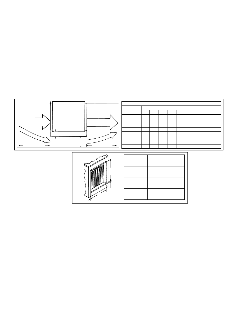
FIGURE 21 - Duct
Connection Dimensions
- inches (mm)
6.0 Mechanical
(cont'd)
6.4 Duct Furnace
Airflow (cont'd)
6.4.3 Constructing a Bypass Duct
When the CFM of air throughput is greater than desirable or permissible for the unit,
a bypass duct may be constructed. Follow these instructions to determine the correct
size of the bypass duct.
1) From the tables in Paragraph 6.4.1, find the pressure drop (P.D.) and the allowable
CFM for the duct furnace that is being installed.
EX: Std Size SC250 @ 50°F Temperature Rise; P.D. 36; CFM 2220
2) Subtract the allowable CFM from the actual CFM of the installation to determine
how much air must be diverted through the bypass duct.
EX: Actual Blower CFM is 3000; 3000 minus allowable CFM of 2220 = 780
3) Go to the column in the bypass CFM chart that is closest to the pressure drop
through the heater. Move down in that column until you find the CFM closest to the
answer in Step 2).
EX: Go to P.D. column .35; move down to 830
4) Move to the left column to find out the required size of the bypass duct.
EX: Bypass Duct should be 3" (76mm).
Top View
of Furnace
Control Side
Bypass Duct A
2 (51mm) minimum
18 (457mm)
18 (457mm)
FIGURE 20 - Bypass Duct
Bypass CFM
"A" Width
Pressure Drop through the Furnace
.10 .15 .20
.25
.30
.35
.40
.45
.50
3" (76mm)
490 530 610 700 780 830 900 960 1010
4" (102mm) 630 750 870 980 1090 1160 1250 1310 1400
5" (127mm) 850 1010 1190 1300 1410 1520 1640 1730 1810
6" (152mm) 1050 1290 1480 1650 1800 1940 2090 2200 2320
7" (178mm) 1250 1510 1760 1960 2180 2320 2500 2650 2800
8" (203mm) 1490 1810 2100 2350 2560 2760 2940 3110 3290
9" (229mm) 1700 2100 2400 2700 2970 3200 3400 3600 3800
10" (254mm) 1920 2350 2760 3090 3650 4020 4300 4550 4800
6.4.4 Duct Connection