Reznor SC Duct Furnace Unit Installation Manual User Manual
Page 29
Form I-SC, P/N 207696 R11, Page 29
8.4.4 Optional
Electronic Modulation
The type and capability of the electronic modulation system, depends on the option
selected. Electronic modulation options are identified by a suffix to the Serial No.
printed on the heater rating plate. AG7 is identified as MV-1; AG8 is identified as MV-3;
AG9 is identified as MV-4; AG21 is identified as MV-A; AG39 is identified as MP-1; and
AG40 is identified as MP-2.
Installation NOTE: Sizes 350 and 400 with electronic modulation require a minimum
of 6" w.c. natural gas supply pressure.
Electronic Modulation between 50% and 100% Firing Rate (Options AG7,
AG8, AG9)
Depending on the heat requirements as established by the thermistor sensor, the
burner modulates between 100% and 50% firing. The thermistor is a resistor that
is temperature sensitive in that as the surrounding temperature changes, the Ohms
resistance changes through the thermistor. This change is monitored by the solid state
control center (amplifier) which furnishes varying DC current to the modulating valve
to adjust the gas input.
Each modulating valve is basically a regulator with electrical means of raising and
lowering the discharge pressure. When no DC current is fed to this device, it functions
as a gas pressure regulator, supplying 3.5" w.c. pressure to the main operating valve.
Refer to the wiring diagram supplied with the furnace for proper wiring connections.
Electronic modulation for heating controlled by a specially designed room thermo-
stat (60°-85°F) is identified as Option AG7. Electronic modulation control systems for
makeup air applications controlled by a field-installed duct sensor (See Paragraph
6.4.5.) and temperature selector (55-90°F) are identified as either Option AG8 or Option
AG9. The temperature selector setting for Option AG8 is on the amplifier; Option AG9
has a remote temperature selector. Both systems are available with an override ther-
mostat.
Computer Controlled Electronic Modulation between 50% and 100%
Firing Rate (Option AG21)
With this option the furnace is equipped with a Maxitrol signal conditioner which oper-
ates much the same way as the amplifier above to control the regulator valve. The con-
ditioner accepts an input signal of either 4-20 milliamps or 0-10 volts from a customer-
supplied control device such as a computer. With the dip switches on the conditioner in
the "on" positions, the conditioner accepts a 4-20 milliamp signal. In the "off" positions,
the conditioner accepts a 0-10V signal. The conditioner converts the signal to the 0 to
20 volt DC current required to control the modulating valve.
Electronic Modulation
between 20 to 28%
and 100% Firing Rate
(U.S. Patent 6,109,255),
Option AG39 - not
available on Size 350;
available with natural gas
only
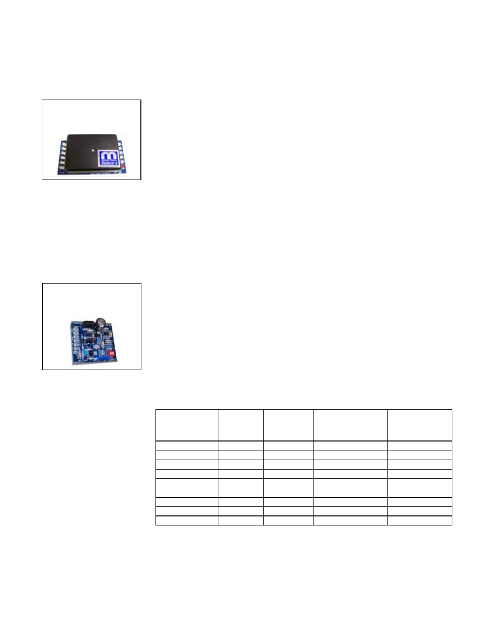
FIGURE 29 - Maxitrol
Signal Conditioner in
Options AG21 & AG40
Depending on the size, furnaces equipped with electronic modulation Option AG39
have a 20-28% turndown ratio. The furnace will ignite at any input rate in the available
range and will maintain average thermal efficiencies equal to or greater than the ther-
mal efficiency at full fire.
The gas train includes a single-stage gas valve, a modulating valve, and two gas pres-
sure switches. The burner rack is equipped with one flash carryover and a regulated
gas lighter tube system. The carryover lighter tube receives its gas supply through the
regulator, simultaneously with the gas to the burner. Control of the system is through a
Maxitrol amplifier with a corresponding remote temperature dial.
Model SC with
AG39 or AG40
Maximum
Turndown
MBH Input
Range
Inlet Pressure to
Modulating Valve
(factory set)
Gas Supply
Pressure
Required
SC 100
20%
20 - 100
3.8" w.c.
5" w.c
SC 125
20%
25 - 125
3.9" w.c.
5" w.c.
SC 150
27%
40.3 - 150
3.7" w.c.
5" w.c.
SC 175
23%
40.3 - 175
3.7" w.c.
5" w.c.
SC 200
26%
51.8 - 200
3.9" w.c.
5" w.c.
SC 225
23%
51.8 - 225
3.9" w.c.
5" w.c.
SC 250
28%
69 - 250
4.0" w.c.
5" w.c.
SC 300
23%
69 - 300
4.0" w.c.
5" w.c.
SC 400
25%
100 - 400
4.4" w.c.
6" w.c.
FIGURE 28 - Amplifier
in Options AG7, AG8,
and AG9