3 troubleshooting – Reznor SC Duct Furnace Unit Installation Manual User Manual
Page 37
Form I-SC, P/N 207696 R11, Page 37
10.2.5 Cleaning the
Heat Exchanger
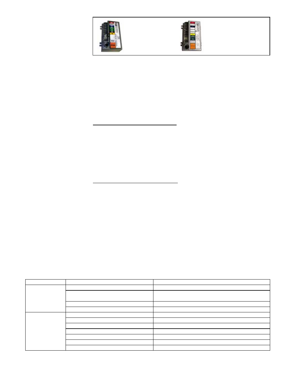
Ignition Controller
with Lockout, UTEC
1003-514, P/N
257010, for Option
AH3 Gas Control
Recycling Ignition
Controller, UTEC
1003-638A, P/N
257009, for Option
AH2 Gas Control
Service NOTE: If replacing
an earlier model of ignition
controller, order replace-
ment kit
P/N 257472 for
a unit with recycling gas
control Option AH2 or
P/N
257473 for Option AH3 gas
control with lockout. (Option
codes are listed on the unit
wiring diagram.)
If the main gas valve fails to open with a normal full size pilot flame established, check
for the following:
a) If voltage between black and brown leads on the main gas valve is 20 to 32 VAC
and there is no main gas flow with the built-in manual valve in FULL OPEN posi-
tion, the main valve is defective.
b) If there is no voltage between black and brown leads on the main gas valve, check
for disconnected or shorted flame sensor lead or flame sensor probe.
When the above conditions are normal and the main gas flow is still off, the ignition
controller is probably defective. Do not attempt to service the ignition controller; it does
not contain any replaceable components.
Outer Surfaces (circulating air side) - To clean the outer surfaces of the heat
exchanger, gain access by removing the inspection panels in the ductwork or remove
the ductwork.
Remove the baffles between the heat exchanger tubes; see
FIGURE 1, page 5.
(
NOTE: If the heater has been converted to high CFM (look for conversion label on the
unit), these baffles will have already been removed.) To remove the baffles, remove
the screws marked "A" in
FIGURE 1, and slide each baffle forward. Use a brush and/or
an air hose to remove accumulated dust and grease deposits from the heat exchanger
tubes and the baffles. Re-install the baffles by sliding them into the slot in the other
end of the heat exchanger and replacing the screws. Secure ductwork as necessary.
Inner Surfaces (combustion gas side) - The inner surfaces of the heat exchanger
can be reached for cleaning with the burner rack removed (See Paragraph 10.2.3.) An
air hose; a long (18 to 24-inch), 1/2" diameter stiff brush; a flashlight; and a mirror are
needed. Clean the inner surface of the heat exchanger from beneath using the brush
to "scrub" the tube walls to remove any accumulated dust, rust, and/or soot.
Re-assemble the furnace. Check for proper operation.
10.2.6 Venter Motor
Power venter motors are permanently lubricated. No oiling is required.
10.2.7 Limit Control
Check
With the heater on, completely block off the distribution air. The limit control should
open within a few minutes, shutting off gas supply to the main burners.
10.3 Troubleshooting
Reference: If the furnace is equipped with electronic modulation Option AG39 or AG40, consult the troubleshooting
chart,
FIGURE 31, page 31.
TROUBLE
PROBABLE CAUSE
REMEDY
Venter motor will
not start
1. No power to the furnace.
1. Turn on power, check supply fuses or circuit breaker.
2. No 24-volt power to venter relay.
2. Turn up thermostat, check control transformer output.
Check for loose or improper wire connections.
3. Venter relay defective.
3. Replace.
4. Defective motor or capacitor.
4. Replace defective part.
Pilot will not light -
- Venter operating
1. Manual valve not open.
1. Open manual valve.
2. Air in gas line.
2. Bleed gas line.
3. Dirt in pilot orifice.
3. Remove and clean with compressed air or solvent.
4. Gas pressure too high or too low.
4. Adjust supply pressure. (See Paragraph 6.2).
5. Kinked pilot tubing.
5. Replace tubing.
6. Pilot valve does not open.
6. If 24 volt is available at the valve, replace valve.
7. No spark:
7.