0 mechanical (cont'd), Horizontal vent instructions, 3 venting and combustion air (cont'd) – Reznor SC Duct Furnace Unit Installation Manual User Manual
Page 14
Form I-SC, P/N 207696 R11, Page 14
HORIZONTAL VENT
INSTRUCTIONS
Components Required - Factory and Field
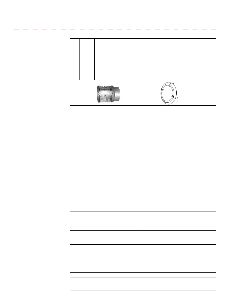
FIGURE 10 - Parts in
the Horizontal Vent
Terminal/Combustion
Air Package (Option
CC6)
Field-supplied
installation
requirements:
• Vent pipes - see requirements, page 10.
• Combustion air pipes - see requirements, page 10.
• Taper-type vent pipe diameter reducers and/or increasers as required.
• Thimble (a thimble is not required if wall is of non-combustible construction).
• Flashing.
• Sheetmetal screws, tape, and sealant as required.
Installation Instructions
for Horizontal Vent Kit
Option CC6
1. Determine the location on the outside wall for the vent terminal. Location must
comply with vent length requirements, Requirement No. 3 on page 10. In most applica-
tions, the terminal would be on a level with the heater mounting height. Allow 1/4" per
foot (6mm per 305mm) downward pitch for condensate drain.
The distance of the termination of the horizontal vent from adjacent public walkways,
adjacent buildings, openable windows, and building openings must be in accordance
with local codes or, in the absence of local codes, must conform with National Fuel
Gas Code Z223.2. Local codes supersede all provisions in these instructions and in
the National Fuel Gas Code. Minimum clearances for the horizontal vent terminal are
shown below. Also, select a location that complies with adjoining building clearances
as shown in
FIGURE 12, page 16.
Products of combustion can cause discoloring of some building finishes and deteriora-
tion of masonry materials. Applying a clear silicone sealant that is normally used to pro-
tect concrete driveways can protect masonry materials. If discoloration is an esthetic
problem re-locate the vent or install a vertical vent.
Clearances to a
Horizontal Vent
Terminal
Screened
Exhaust
Assembly,
P/N 53316
Inlet Guard,
P/N 205894
6.3 Venting and Combustion Air (cont'd)
6.0 Mechanical (cont'd)
Structure
Minimum Clearances for Vent Terminal
Location (all directions unless specified)
Forced air inlet within 10 ft (3.1M)*
3 ft (0.9M) above
Combustion air inlet of another appliance 6 ft (1.8M)
Door, window, or gravity air inlet (any
building opening)
4 ft (1.2M) horizontally
4 ft (1.2M) below
1 ft (305mm) above
Electric meter, gas meter ** and relief
equipment
U.S. - 4 ft (1.2M) horizontally; Canada - 6 ft
(1.8M)
Gas regulator **
U.S. - 3 ft (0.9M); Canada - 6 ft (1.8M)
horizontally)
Adjoining building or parapet
6 ft (1.8M)
Adjacent public walkways
7 ft (2.1M) above
Grade (ground level)
3 ft (.9M) above***
*Does not apply to the inlet of a direct vent appliance. **Do not terminate the vent
directly above a gas meter or service regulator. *** Consider local snow depth
conditions. The vent must be at least 6” (152mm) higher than anticipated snow depth.
Qty
P/N Description
1 205883 Complete Horizontal Vent Kit (Same as Option CC6)
1 205885 Concentric Adapter Box Assembly (See
FIGURE 8, page 12.)
1
53316 Screened Exhaust Assembly (illustrated below)
1 205894 Inlet Guard (illustrated below)
4
37661 #10-16 x 1/2" long Screws to attach the inlet guard
2 207232 Brackets for attaching Concentric Adapter Box (
FIGURE 11, page 15.)
1
53335 Tube of High Temperature (450°F) Silicone Sealant