0 maintenance and service (cont'd), 2 maintenance procedures (cont'd) – Reznor SC Duct Furnace Unit Installation Manual User Manual
Page 36
Form I-SC, P/N 207696 R11, Page 36
Propane - break the lighter tube connection at the regulator and remove the lighter
tube orifice supply tubing; remove the retaining screws in the drip shield and the
shield; remove the retaining screws and slide out the lighter tube.
2. Pull main burners horizontally away from injection opening and lift out.
3. Remove manifold bracket screws and remove manifold.
4. Remove the main burner orifices.
5. Remove screws and lift out pilot burner.
Follow the instructions in Paragraph 10.2.3 to clean. To re-assemble and replace,
reverse the above procedures being careful not to create any unsafe conditions.
CAUTION: When cleaning, wearing eye protection is recommended.
Cleaning Pilot and Main Burners
In the event the pilot flame is short and/or yellow, check the pilot orifice for blockage
caused by lint or dust accumulation. Remove the pilot orifice and clean with air pres-
sure. DO NOT REAM THE ORIFICE. Check and clean the aeration slot in the pilot
burner.
Clean the metal sensing probe and the pilot hood with an emery cloth and wipe off the
ceramic insulator. Check the spark gap; spark gap should be maintained to 7/64". After
the pilot is cleaned, blow any dirt away with compressed air.
Clean main burners and burner orifices using air pressure. Use an air nozzle to blow
out scale and dust accumulation from the burner ports. Alternately blow through the
burner ports and the venturi. Use a fine wire to dislodge any stubborn particles in the
burner ports. Do not use anything that might change the port size.
Clean the burner rack carryover systems with air pressure.
10.2.4 Spark Ignition
System
The ignition controller provides the high voltage spark to ignite the pilot service and also
acts as the flame safety device. After ignition of the pilot gas, the controller electroni-
cally senses the pilot flame. A separate solid metal probe in the pilot burner assembly
is used to sense the flame. A low voltage DC electrical signal is imposed on the metal
probe which is electrically insulated from ground. When the pilot flame impinges on
the sensing probe, the flame acts as a conduction path to ground. This completes the
DC circuit; the ignition controller responds by energizing the main gas valve.
Proper
operation of the electronic spark ignition system requires a minimum flame sig-
nal of .2 microamps as measured by a microampmeter.
CAUTION: Due to high voltage on pilot spark wire and pilot electrode,
do not touch when energized. See Hazard Levels, page 2.
If no spark occurs, check the following:
a) Voltage between Terminals TH and 7 should be at least 20 volts and no higher
than 32 volts. Refer to Troubleshooting (Paragraph 10.3) if no voltage is observed.
b) Short to ground in the high tension lead and/or ceramic insulator.
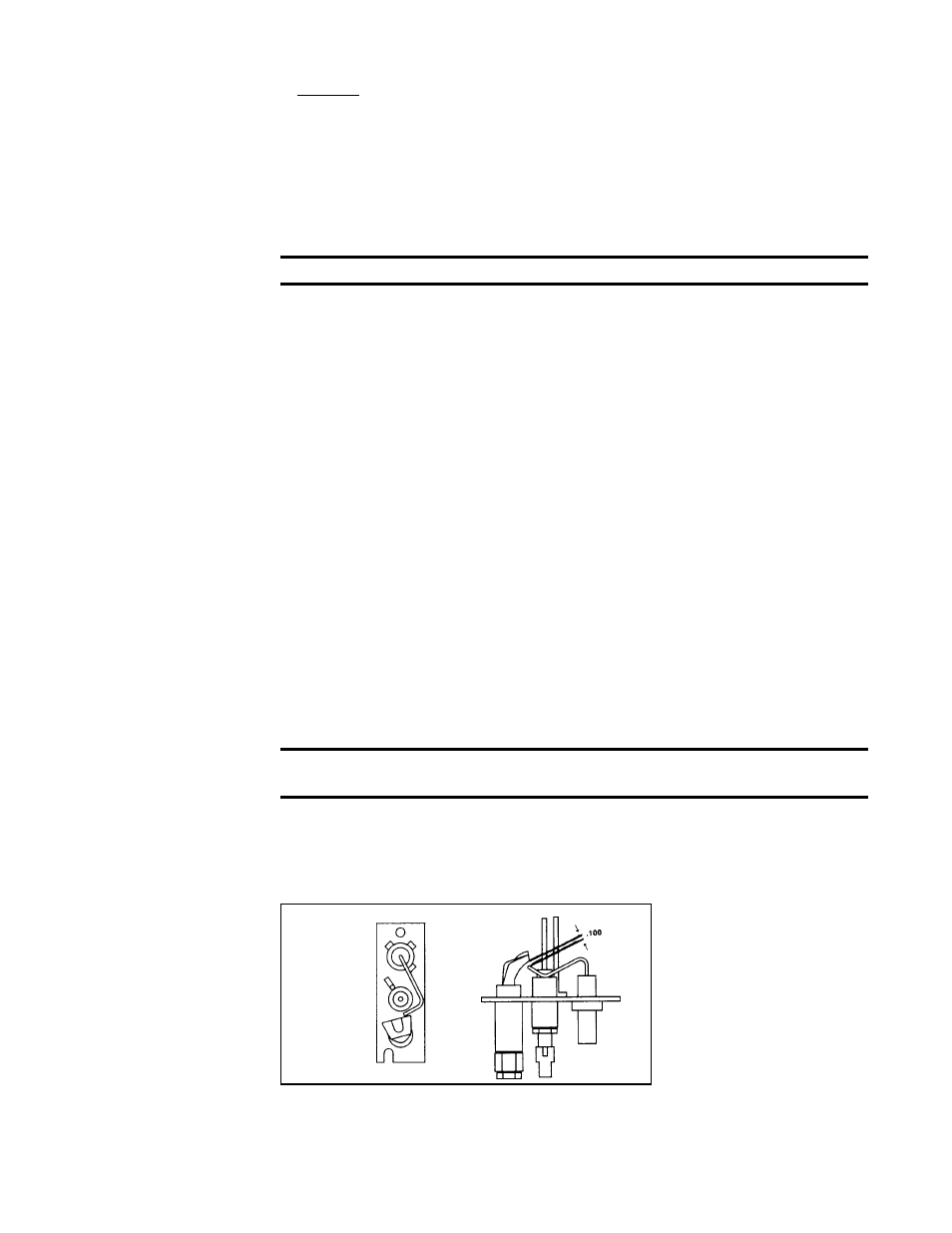
c) Pilot spark gap should be approximately .100". (See
FIGURE 35.)
Top
View
Side
View
FIGURE 35 - Spark Gap
NOTE: When checking for spark with the pilot burner assembly removed from the
burner rack, the pilot assembly must be grounded to the heater for proper spark.
If the above conditions are normal and no spark occurs, replace the ignition control-
ler.
10.0 Maintenance
and Service
(cont'd)
10.2 Maintenance
Procedures
(cont'd)
10.2.3 Burner Rack Removal Instructions (cont'd)