Keri Systems BioPointe Users Manual User Manual
Page 78
Appendix F – TCP/IP Subnet Mask Translation
77
B. Network of BioPointe Devices
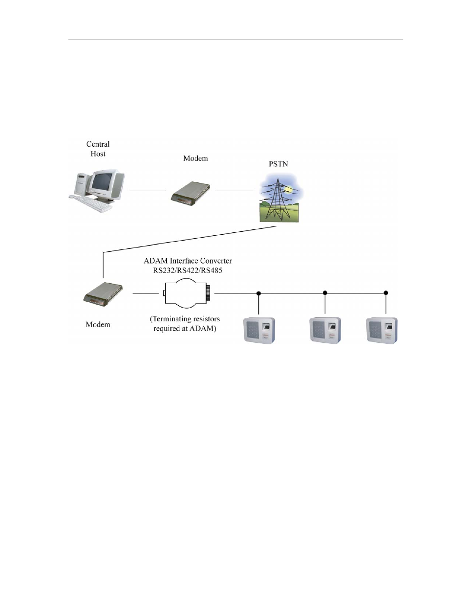
The following schematic shows how a network of devices can be accessed remotely from a central host that is
located geographically apart from the devices that it has to access.
PSTN
BioPointe Mini devices located geographically
together
Schematic diagram of network of BioPointe devices accessed via a modem
The network of BioPointe devices can be connected in RS422 or RS485 configuration as described in
Appendix C. The connection between ADAM and T-Junction box, between T-Junction box and T-Junction box
and at the last T-Junction box are described in the Appendix C.