Keri Systems EntraGuard Gold Quick Reference User Manual
Entraguard gold quick reference, 0 specifications, 0 cable requirements
P/N 01801-003 Rev. A
EntraGuard Gold Quick Reference
This Quick Reference is designed for the experienced installer as a quick reference while installing to
ensure all connections are made properly.
The Quick Reference is designed as a checklist of sorts where you may check off as each installation
procedure is completed. Additional information is given for those who need to be reminded of what is
performed during that part of the installation. For detailed information on installing the EntraGuard
Gold Telephone Entry Controller, see the EntraGuard Gold Quick Start Guide (P/N 01801-001).
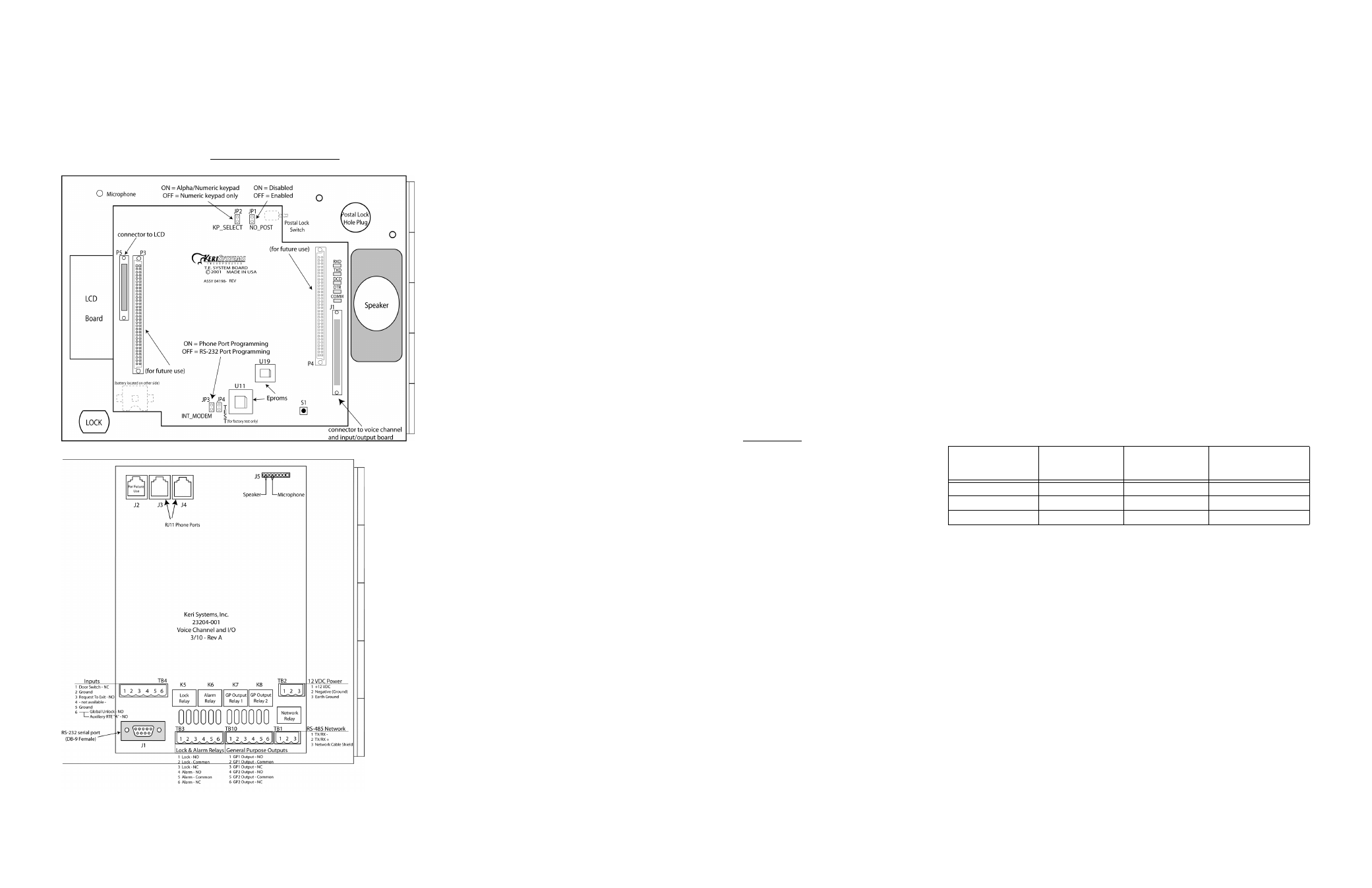
Figure 1: EntraGuard Gold - Main Board
Figure 2: EntraGuard Gold - Voice Channel and I/O Board
1.0
Specifications
Current Draw
• maximum current draw 750 mA for a controller
NOTE: If an electronic locking device (such as a magnetic lock, a door strike, or similar device) is to
be driven by the same power supply as the EntraGuard Gold controller, please ensure the power
supply provides enough current to drive every device connected to that supply plus an adequate safety
margin. AC power cannot be used.
NOTE: Isolation of power supplies may be required with high transient situations.
Users Allowed
• 750 tenants maximum
Event Storage Capacity
• 3,640 events
Keypad
• Alpha Numeric Radiant
• Standard Mechanical
NOTE: When installing the Alpha Numeric Radiant keypad, careful consideration should be given to
each location's ambient lighting. The Radiant keypad may not appear bright enough in direct
sunlight. For locations that will be in prolonged direct sunlight, use the Standard Mechanical keypad.
2.0
Cable Requirements
RS-232 Serial Cable
• four conductor, shielded, stranded, AWG 24 wire (Belden 9534 or a larger gauge)
• 50 foot maximum length (per RS-232 industry specification - greater lengths are not
recommended)
RS-485 Network Cable
• one twisted, shielded pair of conductors, stranded, AWG 24 wire (Belden 9501 or a larger
gauge)
• 4,000 foot total network length (per RS-485 industry specification)
• extended network configurations are possible – refer to the Network Wiring Application Note
(P/N 01824-002) for extended network configurations of up to 5,000 feet per star line and
16,000 feet total network length
Telephone
• 1 pair copper phone line with RJ11 connection
NOTE: EntraGuard Gold is not to be used with a Centrex, PBX, or digital phone line. Only use a
Plain Old Telephone Service (POTS) analog phone line.
Input Power
• two conductor, stranded, AWG 18 wire (Belden 8461 or a larger gauge)
NOTE: On long power cable runs, the cable resistance causes a drop in voltage at the end of the
cable run. Be sure your power supply does provide 12 VDC at the end of the cable run.
Earth Ground
• Single conductor, AWG 18 wire (or a larger gauge) - Ground wire is green, with or without
yellow tracer.
Input and Output Connections
• two conductor, stranded, AWG 22 (or a larger gauge)
NOTE: The Lock Output relay may require a heavier gauge of wire depending upon the current
demands of the lock and the length of the lock wiring run.
NOTE: If plenum cable is required, please reference the Belden plenum equivalent to the cables listed
above.
3.0
EntraGuard Gold: Before Turning Power ON
Verify 12 VDC is supplied to the controller.
1.Verify the power supply is the correct voltage by first setting the tester to AC and checking
the voltage the power supply. If it reads over 1 volt AC, then you will need to use a different
power supply (preferably linear).
2.Set the DVM to a DC volt scale capable of reading 12 VDC.
3.Turn the power supply ON.
4.Place the Red DVM lead on the power supply’s terminal block output - Pin 1. Place the
Black DVM lead on the power supply’s terminal block output - Pin 2. Check the DVM
reading. It should read between +12 VDC to +14 VDC.
5.If the DVM does not read between +12 VDC to +14 VDC, verify the power supply is of the
correct voltage (see step 1 above), verify the cable length does not exceed 200 feet, and
verify the cable gauge is AWG 18. This problem must be corrected before power can be
supplied to the controller.
6.Turn the power supply OFF.
7.Connect the power supply’s terminal block output to the TB-2 connector on the EntraGuard
Gold Voice Channel and I/O board.
8.The controller is now ready to be powered ON.
NOTE: On long power cable runs, keep in mind the resistance in the cable itself causes a drop in
voltage at the end of the run. The power supply must be able to account for this voltage drop.
Verify all wiring connections are secure and are made to the correct Terminal Block pins.
Verify a good earth ground has been connected to TB-2, pin 3.
If the controller is not using a door contact switch, verify a door switch input jumper is
connected between TB-4, pins 1 and 2.
Verify transient suppression has been installed on all electrical devices connected to a
controller’s outputs.
Verify the JP3 INT_MODEM jumper is properly set for communication between the master
controller and host computer.
• Jumper should be ON JP3 for use of the RJ11 phone port
• Jumper should be OFF JP3 for use of the RS-232 port (either direct connect or with a modem)
3.1
Recommended Power Supplies
Manufacturer
Description
Model Number
Keri Systems Part
Number
ESD
12 Volt – 2 Amp
LP-2
KPS-5
ESD
12 Volt – 10 Amp
LP-10
KPS-11
Golden Pacific
12 Volt – 1.2 Amp
PD-1212AR
KPS-7