2 dip switches – Keri Systems BioPointe Users Manual User Manual
Page 53
Configuring the BioPointe
52
6.2 DIP Switches
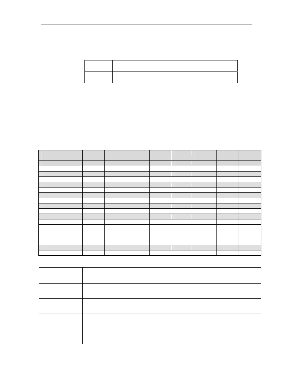
There are three DIP switches on the control board. The usage of each switch is as tabulated:
SW1
8-way
To set the Device ID
SW2
4-way
To set the baud rate and communication type
SW3
8-way
To set the type of serial communication (i.e.
whether RS232, 422 or 485)
The following tables show the settings for each of the three DIP switches.
Note that a "-"indicates an "OFF" position.
Table 1: SW1 (Device ID)
SW1 is used to set the Device ID of the device. It has a row of 8 DIP switches. The range of Device IDs that
can be set is 0 to 255. However, the acceptable range for field operation is 1 to 254. The Device ID is set
according to the binary format of an 8-bit byte. An "ON" position is interpreted as binary bit 0. To help you
to find the dip switching settings for a particular Device ID, use the index value associated with each bit.
Switch /
Device ID
1
2
3
4
5
6
7
8
Index Value
1
2
4
8
16
32
64
128
0
(Not
used) ON ON ON ON ON ON ON ON
1
-
ON
ON
ON
ON
ON
ON
ON
2
ON - ON
ON
ON
ON
ON
ON
3
-
-
ON
ON
ON
ON
ON
ON
4
ON
ON - ON
ON
ON
ON
ON
5
-
ON
-
ON
ON
ON
ON
ON
6
ON - - ON
ON
ON
ON
ON
7
-
-
-
ON
ON
ON
ON
ON
8
ON ON ON - ON ON ON ON
9
-
ON
ON
-
ON
ON
ON
ON
10
ON - ON - ON
ON
ON
ON
:
:
:
:
:
:
:
:
:
253
- ON - - - - - -
254
ON
-
-
-
-
-
-
-
255
(Not
used) - - - - - - - -
Examples:
Switch/
Device ID
1 2 3 4 5 6 7 8
Index
Value
1 2 4 8 16 32 64 128
Device
ID
5 = 1 + 4
Position
- ON - ON ON ON ON ON
Device
ID
6 = 2 +
4
Position
ON - - ON ON ON ON ON
Device ID 10
=
2
+
8
Position ON - ON
- ON
ON
ON
ON
Device
ID
30 =
2 +
4 +
8 +
16
Position ON - - - -
ON
ON
ON