J4 inputs, J5 inputs – Carrier RTU OPEN 11-808-427-01 User Manual
Page 22
Installation
16
RTU Open
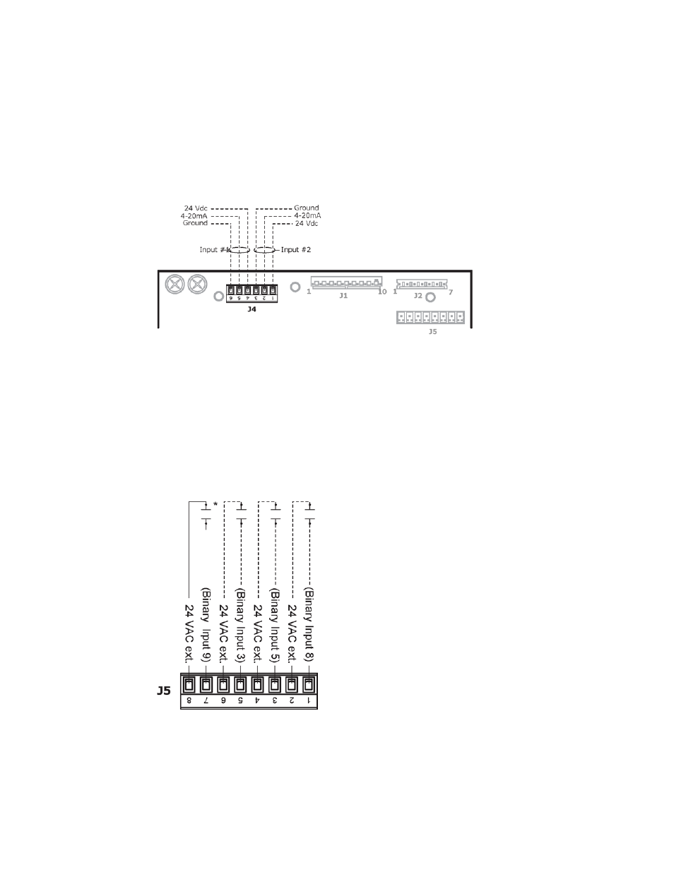
J4 Inputs
1
Turn
off
the RTU Open's power.
2
Connect the input and output wiring to the screw terminals on the RTU Open.
NOTE
When utilizing the controller's 24 Vdc auxiliary power out, the total current demand for these two
input channels must not exceed 40 mA (100mA per channel).
NOTE J4
Analog Inputs 1 and 2 may be set for the following device types:
○
IAQ Sensor
○
OAQ Sensor
○
Space RH Sensor
J5 Inputs
The terminals for Inputs 3, 5, and 8 are available for use in place of the flying wire leads at Molex
connectors
J1
and
J2
identified below:
See also other documents in the category Carrier Conditioners:
- 42S (72 pages)
- 30GT (4 pages)
- 48SS060 (8 pages)
- 50ME (54 pages)
- 38AH024-034 (26 pages)
- ZC (28 pages)
- 30GA (12 pages)
- COMFORTLINK 48A2 (8 pages)
- 48HE003---006 (64 pages)
- 33ZCSECTRM (52 pages)
- 19XRV (40 pages)
- MODU-PAC 50DF (37 pages)
- 17DA (8 pages)
- SINGLE PACKAGED ELECTRIC COOLING UNITS 50GS (28 pages)
- 48JZ (N) 024-060 (30 pages)
- 30GX080-176 (8 pages)
- 50DL (24 pages)
- 50GL-A (4 pages)
- NP034-074 (72 pages)
- 40GXQ (12 pages)
- 30XA080-500 (8 pages)
- 39E (12 pages)
- 40KMQ------301 (10 pages)
- 38AE (12 pages)
- 48AW (118 pages)
- 38GXQ (28 pages)
- 48ES---A (38 pages)
- 48GL (22 pages)
- 48GH (22 pages)
- 40QA024-060 (24 pages)
- TJF004 (52 pages)
- 39LD (40 pages)
- 48DL (4 pages)
- 48/50TC04---28 (44 pages)
- 50EJ (56 pages)
- 17EX (120 pages)
- 50BA (24 pages)
- 50BB (16 pages)
- 50BB (8 pages)
- 50BJ (20 pages)
- 30H (16 pages)
- 48HJD005-007 (48 pages)
- 50ZP (6 pages)
- 50DP016 (16 pages)
- 50LJ008-014 (19 pages)