EVCO EPU2LXP1CH User Manual
Page 20
EVCO S.p.A.
c-pro 3 micro and c-pro 3 kilo | Hardware manual ver. 1.0 | Code 114CP3UKE104
page 20 of 62
The following table shows the function codes supported by the controller.
Function
code
Meaning
FC 01
read coils
FC 02
read discrete inputs
FC 03
read multiple registers
FC 04
read input registers
FC 05
write single coil
FC 06
write single register
FC 08
diagnostic
FC 15
write multiple coils
FC 16
write multiple registers
FC 23
read write multiple registers
For the settings about the RS-485 port look at chapter 6 “CONFIGURATION”.
The maximum number of devices that can make a CAN network (32) depends on the bus load; the bus load depends on the baud rate
of the CANbus communication and on the kind of device in the network.
For example: a CAN network can be made of a programmable controller, of four I / O expansions and of four user interfaces
with baud rate 500,000 baud.
Connect the CAN port using a twisted pair.
For the settings about the CAN port look at chapter 6 “CONFIGURATION”.
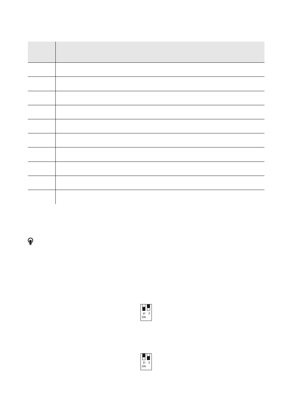
Termination RS-485 port and termination CAN port
Micro-switch to:
-
plug in the termination of the CAN port (120
Ω, 0,5 W); position micro-switch 2 on position ON to plug in the termination of the
CAN port (plug in the termination of the first and of the last element of the network).
-
to plug in the termination of the RS-485 port with Modbus slave communication protocol (120
Ω, 0.25 W); position micro-
switch 1 on position ON to plug in the termination of the RS-485 port (plug in the termination of the first and of the last element
of the network).