Serial terminal (4) loopback signals, Connecting serial devices, Serial terminals (8) - 2e – Comtrol UP DeviceMaster Installation User Manual
Page 49: Serial terminal (8) connectors, Als (4). see
Hardware Installation and Configuration Guide: 2000451 Rev. J
Connecting Serial Devices - 49
Connecting Serial Devices
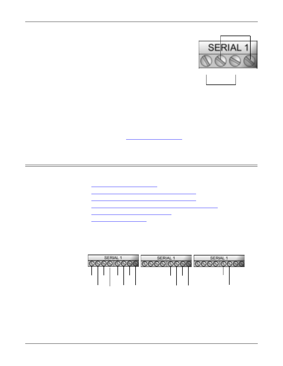
Serial Terminal (4)
Loopback Signals
Use this drawing to wire a loopback, which is used
in conjunction with application software to test
serial ports.
Wire the terminals together to create a loopback.
•
TxD to RxD
•
RTS to CTS
Connecting Serial
Devices
Use the following information to connect the DeviceMaster UP 2-port 1E with
serial terminals.
1.
Connect your serial devices to the appropriate serial port on the DeviceMaster
UP using the appropriate cable. You can build your own cables or loopbacks
using the appropriate discussions.
Note: Refer to the hardware manufacturer’s installation documentation if you
need help with connector pinouts or cabling for the serial device.
2.
on Page 84 for information about
the LEDs.
Serial Terminals (8) - 2E
This subsection discusses the following topics for the DeviceMaster UP 2-port 2E
with serial terminals (8).
•
Serial Terminal (8) Connectors
•
Serial Terminal (8) Null-Modem Cables (RS-232)
•
Serial Terminal (8) Null-Modem Cables (RS-422)
•
Serial Terminal (8) Straight-Through Cables (RS-232/485)
•
Serial Terminal (8) Loopback Signals
•
Serial Terminal (8)
Connectors
Use the following drawings or table for signal information. The signals for
SERIAL2 are the same as SERIAL1.
TxD
RxD
RTS
CTS
RS-232†
RS-422
RS-485 Full-Duplex
RS-485 Half-Duplex
CD
DSR
RI
TxD
RTS
RxD
CTS
DTR
TxD-
TxD+
RxD-
RxD+
TRxD-
TRxD+
† RS232 ground must be connected to the appropriate signal ground terminal.