Port - enclosed installation – Comtrol UP DeviceMaster Installation User Manual
Page 14
14 - Hardware Installation
Hardware Installation and Configuration Guide: 2000451 Rev. J
Hardware Installation
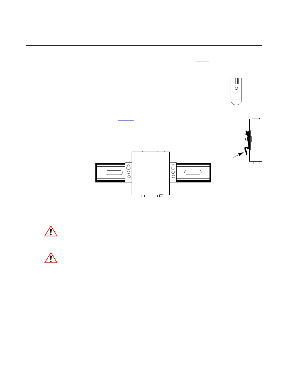
1-Port - Enclosed Installation
Use the following procedure to install the DeviceMaster UP 1-Port.
1.
Place the 1-Port on a stable surface and skip to
or optionally mount the
DeviceMaster UP using the mounting flanges or DIN rail adapters.
a.
Pick up the DeviceMaster UP so that the front of the device is facing you.
b.
Pick up a DIN rail clip. (The three tines should be on top
and the M4 label should face you.)
c.
Slide the DIN rail clip behind the DeviceMaster UP and
line it up with one of the screw holes on the
DeviceMaster UP.
d.
Insert the M4 screw into the hole and tighten with a
Phillips screwdriver.
e.
through d with the second DIN rail clip.
Make sure the screws on both DIN rail clips line up.
Note: If you need to remove the DeviceMaster UP from
the DIN rail, exert pressure on the backside of the
tabs at the bottom of both DIN rail clips.
f.
Attach the DeviceMaster UP to the DIN rail.
Note: Do not connect multiple units until you have changed the default IP
address, see
Initial Configuration
on Page 35.
2.
Connect the DeviceMaster UP port labeled 10/100 ETHERNET to the same
Ethernet network segment as the PLC using a standard network cable.
The default serial port setting on the DeviceMaster UP is RS-232. Do
not connect serial devices until you have configured the serial port
settings. You must first configure the network and then upload the
firmware before you can configure serial port settings.
3.
Apply power to the DeviceMaster UP using the following procedure.
Note: See
on Page 74, if you want to provide your own power supply.
Observe proper ESD techniques when connecting and disconnecting
the DeviceMaster UP.
•
Insert the earth ground wire into the earth ground screw terminal.
M4
DIN Rail
Clip
Side
Press
here
Front
View
DeviceMaster
Caution
Caution