8 air flow fault test, Figure 5.5, Blower proof switch location and wiring – AERCO KC Series Equipped with C-More Controller for Massachusetts Only User Manual
Page 42: 9 ssov proof of closure switch, Figure 5.6, Ssov actuator cover screw location, Safety device testing
SAFETY DEVICE TESTING
5-4
5.8 AIR FLOW FAULT TEST
1. Start the unit in manual mode and set the
valve position between 25% and 30%.
2. Once the unit has proved flame, remove
either wire #154 or #155 from the blower
proof switch (see Fig. 5.5) located on the
air/fuel valve.
3. The unit should shut down and display
AIRFLOW FAULT DURING RUN.
4. Replace the wire previously removed from
the blower-proof switch and depress the
CLEAR button. The unit should restart.
WARNING!
ELECTRICAL VOLTAGES IN THIS
SYSTEM INCLUDE 120 AND 24 VOLTS
AC. POWER MUST BE REMOVED PRIOR
TO PERFORMING WIRE REMOVAL OR
OTHER TESTING PROCEDURES THAT
CAN RESULT IN ELECTRICAL SHOCK.
154
155
AIR/FUEL VALVE
BLOWER PROOF
SWITCH
TO FRAME
HARNESS
Figure 5.5
Blower Proof Switch Location and Wiring
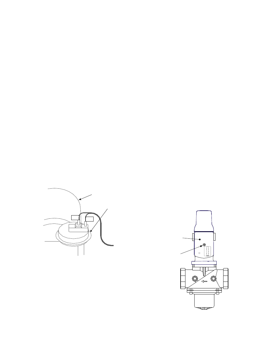
5.9 SSOV PROOF OF CLOSURE
SWITCH
1. Set the unit’s
ON/OFF switch to the OFF
position. Place the unit in manual mode and
set the valve position between 25% and
30%.
2. Remove the Safety Shut-Off Valve (SSOV)
cover to access the terminal connections.
See Fig. 5.6. For units with IRI gas trains,
access the terminal connections of the
downstream SSOV (see drawing SD-A-606
in Appendix E).
3. Remove either wire #149 or #148 from the
SSOV.
4. The unit should fault and display SSOV
SWITCH OPEN.
5. Replace the wire previously removed and
depress the
CLEAR button.
6. Start the unit.
7. Remove the wire again when the unit
reaches the purge cycle.
8. The unit should shut down and display
SSOV FAULT DURING PURGE.
9. Replace the wire on the SSOV and depress
the
CLEAR button. The unit should restart.
SSOV
ACTUATOR
COVER
SSOV
COVER
SCREW
Figure 5.6
SSOV Actuator Cover Screw Location