Figure 4.1, 1/4” gas plug location, 3 preparing the flue vent probe hole – AERCO KC Series Equipped with C-More Controller for Massachusetts Only User Manual
Page 32: Figure 4.2, Analyzer probe hole location, 3 natural gas combustion calibration, Initial start-up
INITIAL START-UP
4-2
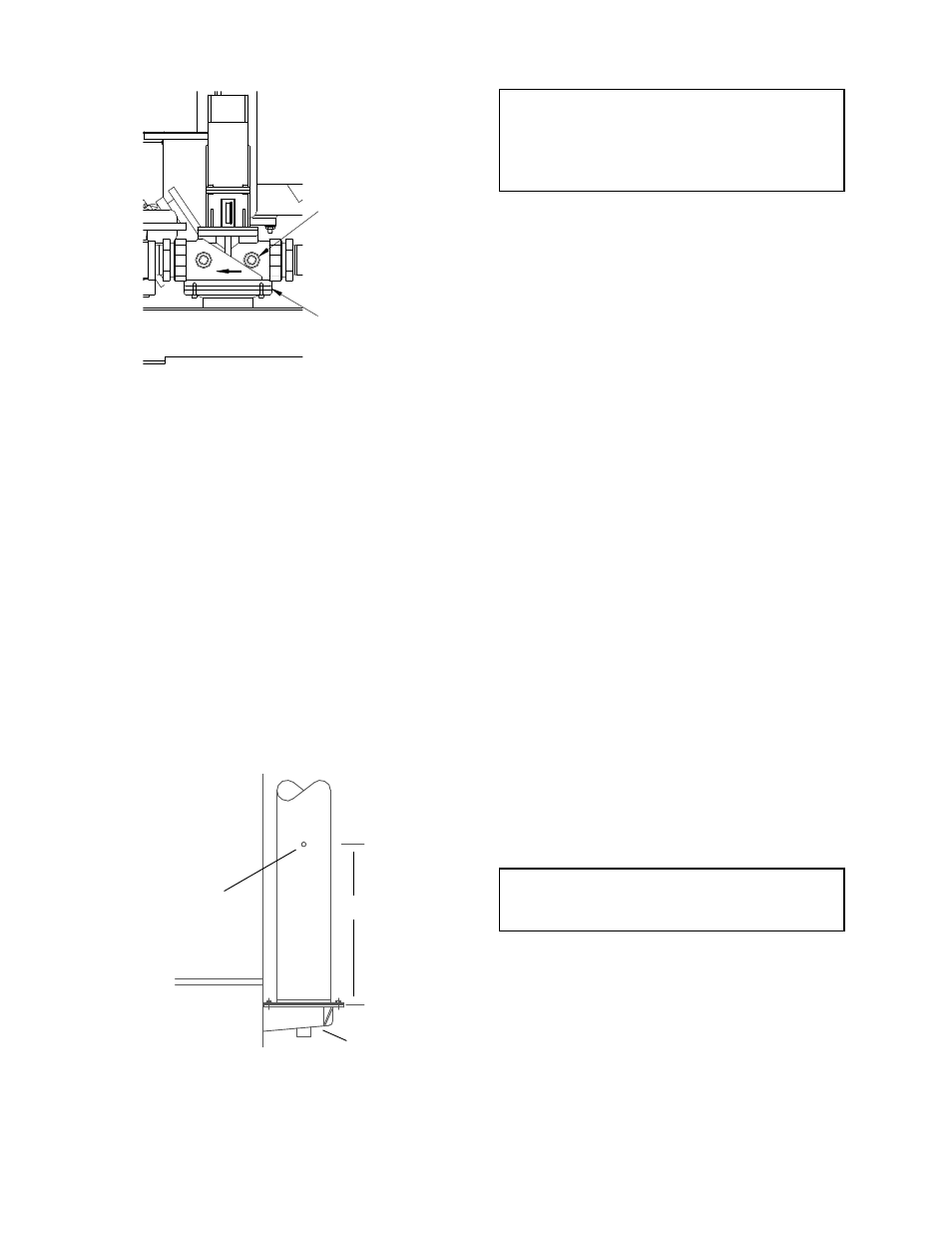
SSOV
1/4" NPT PLUG
(INSTALL
MANOMETER
HERE)
Figure 4.1
1/4” Gas Plug Location
4.2.3 PREPARING THE FLUE VENT
PROBE HOLE
1. If the unit has been installed using the
recommended AL29-4C vent, there will be a
3/8” hole, 18” to 24” above the exhaust
manifold. The outer vent section, that covers
vent section connections must be loosened
and slid down to uncover the hole (see
Fig. 4.2).
2. If equipped with one, adjust the stop on the
combustion analyzer probe so that it extends
into the flue gas flow without hitting the
opposite wall of the flue. Do not insert the
probe at this time.
3/8" - 1/2"
HOLE FOR
COMBUSTION
ANALYZER
PROBE
EXHAUST
MANIFOLD
12" - 18"
Figure 4.2
Analyzer Probe Hole Location
IMPORTANT
The unit is shipped from the factory set up for
either natural gas or propane, as specified by the
Style No. on the Sales Order.
For propane units, refer to paragraph 4.4.
4.3 NATURAL GAS COMBUSTION
CALIBRATION
The KC-1000 is shipped combustion calibrated
from the factory. Recalibration as part of a start-
up is necessary due to altitude, gas BTU
content, gas supply piping and supply regulators.
Factory test data sheets are shipped with each
unit as a reference.
The following combustion calibration procedure
closely follows the factory procedure. By
following this procedure readjustment of
combustion will be kept to a minimum.
1. Open the supply and return valves to the unit
and ensure that the system pumps are
running.
2. Open the gas supply valve(s) to the unit.
3. If a lockup style regulator is installed as a
gas supply regulator, adjust the gas supply
until a reading of 12” W.C. static pressure is
obtained.
4. Set the
ON/OFF switch in the OFF position.
Turn on AC power to the unit. The display
will show LOSS OF POWER and the time
and date.
5. Set the unit to the Manual Mode by pressing
the
AUTO/MAN switch. A flashing Manual
Valve Position message will be displayed
with the present rate in %. Also, the
MANUAL LED will light.
NOTE:
For a review of control panel operating
procedures, see Section 3.
6. Adjust the rate to 0% by pressing the
▼
arrow key.
7. Set the
ON/OFF switch to the ON position.
8. Change the valve position to 25% using the
▲ arrow key. This will put the unit into the
starting sequence.