Air shutter locking nut location, Initial start-up – AERCO KC Series Equipped with C-More Controller for Massachusetts Only User Manual
Page 34
INITIAL START-UP
4-4
17. If necessary, repeat the adjustment until the
oxygen level is within the range specified in
Table 1.
18. Replace the regulator cap and cap gasket.
NOTE:
Adjust only the differential regulator at 30%
control signal; do not adjust the air shutter.
19. Once the oxygen level is within the specified
range at 30%, change the valve position to
13%.
20. Oxygen levels at the 13% valve position
should be as shown in Table 2. No
adjustment should be necessary. Contact
the Factory if the oxygen or carbon
monoxide levels are not within the specified
range.
Table 2
Combustion Oxygen Levels for a 13%
(Natural Gas) and 16% (Propane) Valve
Position
Inlet Air
Temp
Oxygen
(+0.2/-1.0)
Carbon
Monoxide
-20°F
<12 %
<50 ppm
0°F
<12 %
<50 ppm
10°F
<12 %
<50 ppm
30°F
<12 %
<50 ppm
50°F
<11 %
<50 ppm
60°F
<11 %
<50 ppm
70°F
<11 %
<50 ppm
80°F
<11 %
<50 ppm
90°F
<10 %
<50 ppm
100°F
<10 %
<50 ppm
21. Change the valve position to 100%. After the
combustion analyzer has settled, compare
the measured oxygen level with the levels in
Table 3.
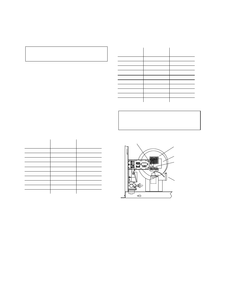
22. If the measured oxygen reading is below the
oxygen range in Table 3, loosen the two
bolts that secure the inlet air shutter to the
unit using a 7/16” wrench (see Fig. 4.4).
Open the shutter 1/4” to 1/2” to increase the
oxygen level, then tighten the nuts.
23. Wait for the analyzer to settle and then
compare the new oxygen reading to Table 3.
Repeat the inlet air shutter adjustment until
the oxygen is within the specified range.
Firmly tighten the inlet air shutter locking
nuts when finished.
Table 3
Combustion Oxygen Levels for a 100%
Valve Position
Inlet Air
Temp
Oxygen
(+0.2/-1.0)
Carbon
Monoxide
-20°F
6.5 %
<150 ppm
0°F
6.3 %
<150 ppm
10°F
6.2 %
<150 ppm
30°F
5.8 %
<150 ppm
50°F
5.4 %
<150 ppm
60°F
5.2 %
<150 ppm
70°F
5.0 %
<150 ppm
80°F
4.8 %
<150 ppm
90°F
4.6 %
<150 ppm
100°F
4.4 %
<150 ppm
REMINDER:
At 30% valve position adjust only the differential
pressure regulator. At 100% valve position,
adjust only the inlet air shutter.
BLOWER
OUTLET
BLOWER
INLET
SCREEN
SHUTTER
SHUTTER
LOCKING NUTS
Figure 4.4
Air Shutter Locking Nut Location
22. If the measured oxygen reading is above the
oxygen range in Table 3, loosen the two
7/16" locking nuts securing the inlet air
shutter. Close the air shutter 1/4” to 1/2” to
decrease the oxygen level and tighten the
two nuts.
23. Allow the analyzer to settle and then
compare the new oxygen reading to Table 3.
24. Repeat the adjustment until the oxygen is
within the specified range. Firmly tighten the
inlet air shutter locking nuts when finished.