Start/stop levels, Control panel operating procedures – AERCO KC Series Equipped with C-More Controller for Massachusetts Only User Manual
Page 29
CONTROL PANEL OPERATING PROCEDURES
3-9
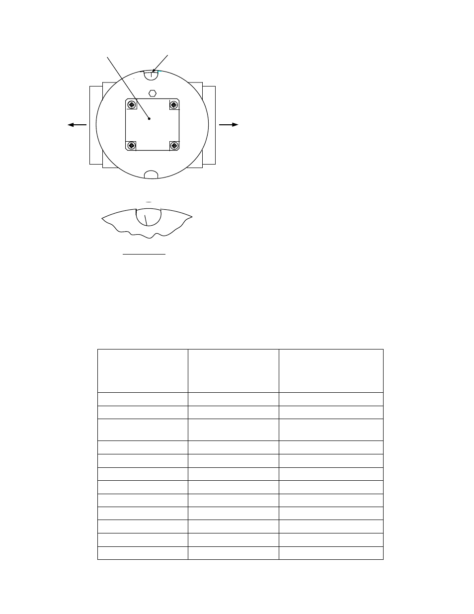
STEPPER
MOTOR
DETAIL "A"
DIAL
(DETAIL “A”)
BL
O
W
E
R
BU
R
N
ER
25
Figure 3-6.
Air/Fuel Valve In Ignition Position
8. With the unit firing properly, it will be
controlled by the temperature controller cir-
cuitry. The
VALVE POSITION will be
continuously displayed on the front panel
bargraph.
9. Once the demand for heat has been
satisfied, the Control Box will turn off the gas
valve. The blower relay will be deactivated
and the Air/Fuel Valve will be closed.
Standby will be displayed.
3.9. START/STOP LEVELS
The start and stop levels are the valve position
percentages that start and stop the unit, based
on load. These levels are Factory preset as
follows for natural gas and propane units:
•
Start Level:
20% (All units)
•
Stop Level:
13% (Natural Gas)
•
Stop Level:
16% (Propane)
Normally, these settings should not require
adjustment.
Note that the energy input of the boiler is not
linearly related to the valve position percentage
(Air/Fuel Valve position). Refer to Table 3-6 for
the relationship between the energy input and
valve position percentage of a unit running on
natural gas.
Table 3-6.
Relationship Between Air/Fuel Valve Position and Energy Input of a Unit Running on Natural Gas
Valve Position,
Air/Fuel Valve
Position
(% Open)
Energy Input
(BTU/Hr)
Boiler Energy Input
(% of Full Capacity)
0
0
0
10
0
0
13
(Stop Level)
50,000
5 %
20
89,000
9%
30
191,000
19%
40
311.000
31%
50
460,000
46%
60
600,000
60%
70
699,000
70%
80
836,000
84%
90
955,000
96%
100
1,000,000
100%