Figure 4.3, Initial start-up – AERCO KC Series Equipped with C-More Controller for Massachusetts Only User Manual
Page 33
INITIAL START-UP
4-3
NOTE:
On initial start-up, or return to service from a
fault condition, the unit will remain at a 29%
valve position for two-minutes.
9. Following the warm-up period, increase the
valve position in 20% increments while
monitoring the gas pressure after every
increase. If gas pressure dips below 8.5”
W.C. for FM gas trains and 8.9” for IRI gas
trains at any input percentage, stop and
raise the pressure. Once 100% is reached,
adjust the gas pressure for 8.5” W.C. or 8.9”
W.C.
NOTE:
If 8.5” W.C. for FM gas trains or 8.9” W.C. for IRI
gas trains cannot be obtained at the 100% valve
position, it will be necessary to stop calibration
and contact the local AERCO representative in
your area. Running the unit on insufficient gas
pressure will void the warranty.
10. Once 8.5” W.C. or 8.9” W.C. is set at the
100% level change the valve position to
30%. Insert the combustion analyzer probe
into the stack.
NOTE:
Always go to a percentage of valve position from
the same direction, (i.e., 100% to 30% or 30% to
20%). Whenever going to a valve position from
below (i.e., 20% to 30%), first go above then
back down to the desired valve position. This is
necessary due to hysteresis in the air/fuel
stepper motor. Hysteresis causes the air/fuel
valve to stop in a slightly different position if the
valve position percentage is approached from
below or above. This results in a difference in
oxygen readings for the same valve position
percentage causing unnecessary recalibration
.
11. Allow enough time for the combustion
analyzer to settle. Compare the measured
oxygen level to the oxygen range for intake
air temperature in Table 1.
12. If the measured oxygen level is within the
range in Table 1, no adjustment is
necessary. Proceed to step 19.
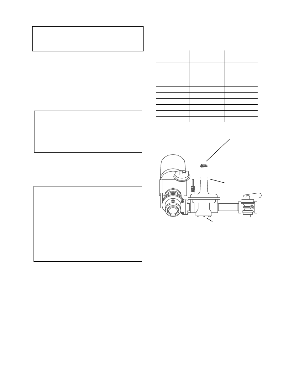
13. If the measured oxygen level is not within
the range listed in Table 1, remove the
regulator cap and cap gasket from the
differential pressure regulator (see
Figure 4.3) and proceed to step 14.
Table 1
Combustion Oxygen Levels for a 30%
Valve Position
Inlet Air
Temp
Oxygen
(+0.2/-1.0)
Carbon
Monoxide
-20°F
7.5 %
<50 ppm
0°F
7.3 %
<50 ppm
10°F
7.2 %
<50 ppm
30°F
6.8 %
<50 ppm
50°F
6.4 %
<50 ppm
60°F
6.2 %
<50 ppm
70°F
6.0 %
<50 ppm
80°F
5.8 %
<50 ppm
90°F
5.6 %
<50 ppm
100°F
5.4 %
<50 ppm
DIFFERENTIAL
PRESSURE
REGULATOR
REGULATOR CAP
CAP GASKET
Figure 4.3
Differential Regulator Adjustment Tool
Installation
14. Use a flat-tip screwdriver to adjust the
differential pressure regulator. Turn the
screwdriver:
•
counterclockwise to increase the
oxygen level
•
clockwise to decrease the oxygen level
15. Replace the regulator cap and cap gasket
and wait for the analyzer reading to settle.
16. When the analyzer reading settles, compare
the new oxygen reading to Table 1.