Stereo module, 0 power indicator, 0 phantom indicator – Yamaha RM800 User Manual
Page 11: 0 pfl/afl indicator, 0 2tr in, moni/aux 5-6, st switches, 0 control room control, Phones jack, 0 phones control, 0 on switch, 0 fader
Attention! The text in this document has been recognized automatically. To view the original document, you can use the "Original mode".
8
Touring Around RM800
POWER
O
PHANTOM
O
PFL/AFL
O
2TR IN Q
□
st
D
MONI/ I I
AUX 5-6 '------- '
0 ' '10
CONTROL ROOM
ON
□
»___(
2
)
__ m)
—0
mwwwwwww^^^
_<6)
«_(8)
Stereo Module
0 POWER Indicator
This POWER indicator lights up when RM800 is powered ON ready for use.
0 PHANTOM Indicator
This PHANTOM indicator lights up when the 48V phantom power is ON.
0 PFL/AFL Indicator
This PFL/AFL indicator lights up when a PFL or AFL switch is pressed.
0 2TR IN, MONI/AUX 5-6, ST Switches
These switches select the signal source for the CONTROL ROOM OUT and
PHONES (headphone jack). You can select only one source at a time.
2TR IN: This switch selects the 2TR IN inputs, allowing you to monitor the
output of your master recorder. You can use it during mixdown recording for
confidence monitoring, or after recording for master playback.
MONI/AUX 5-6: This switch selects MONI/AUX 5-6, allowing you to monitor
the MONI/AUX 5-6 output.
ST: This switch selects the stereo output for monitoring.
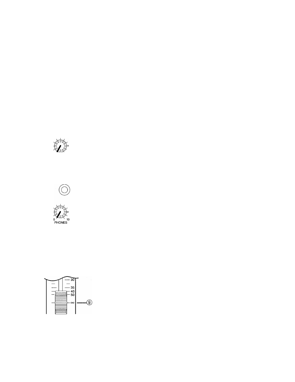
0 CONTROL ROOM Control
This control adjusts the level of the CONTROL ROOM outputs (i.e. the vol
ume of the control room monitors).
© PHONES Jack
A stereo pair headphones can be connected hear for monitoring. The head
phone signal is always the same as the CONTROL ROOM signal, although its
level is controlled by the PHONES control, not the CONTROL ROOM con
trol.
0 PHONES Control
This control adjusts the headphone volume.
0
ON Switch
This switch turns the stereo output ON and OFF; up for OFF and down for
ON.
0
Fader
This fader controls the level of the STEREO OUT. The ‘0’ position indicates the
unity gain setting (i.e. no gain, no attenuation).
RM800 User's Guide