Kontron CG1200 Carrier Grade Server User Manual
Page 70
64
Kontron CG1200 Carrier Grade Server Installation and Maintenance Guide 64
- LED/Switch board power and signal cable
- TAM signal cable
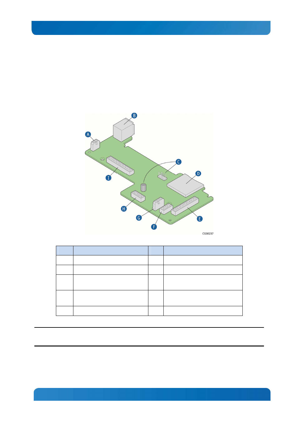
Figure 52 shows the location of all the connectors on the FP board. There are also three standoffs that
fasten the board to the chassis floor. This includes the hex standoff on the FP board that is used to
support an optional eUSB module.
Figure 52: Front Panel Board Connectors
Item
Description
Item Description
A
Front panel board power cable
F
FP board USB cable
B
Dual USB ports
G
HDD LED signal cable
C
eUSB flash connector and standoff
(optional)
H
TAM signal cable
D
SD Module
I
LED/switch board power and signal
cable
E
SSI front panel board power
CAUTION: Before replacing any of the boards on the CG1200 server, you must first take the server out of
service, turn off all peripheral devices connected to the server, turn off the server by pressing the power
button, and unplug the power cord(s) from the system and wall outlet.
When handling the FP board, observe the normal safety and ESD precautions. See Appendix A: Safety
Information for more information.