Kontron CG1200 Carrier Grade Server User Manual
Page 13
7
Kontron CG1200 Carrier Grade Server Installation and Maintenance Guide 7
Table 2: CG1200 Server Components
Item Description
Item Description
A
PCI fan (one pair)
J
CPU/memory fans (four pairs)
B
SAS hard drive bay
K
USB ports (two)
C
Intel® S2400EP4 Server Board
L
Front panel switches and indicators
D
CPU 1
M
SD media slot
E
CPU 2
N
Front panel board
F
PCIe FH/FL riser card assembly
O
Telco alarm module (TAM) board
G
Eight DDR3 memory DIMM slots, two banks of
four DIMMs for each processor
P
RAID module connector
H
Redundant, hot-swappable AC or DC power
supply modules
Q
PCIe slot
I
Power distribution board (PDB)
2.2
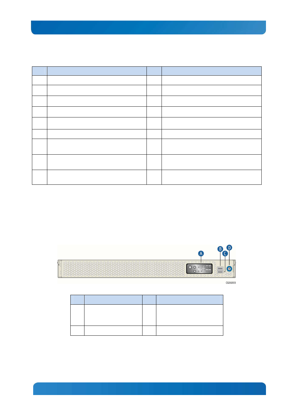
CG1200 Server Front Panel
Figure 3 shows the front panel of the CG1200 server with the bezel installed.
Figure 3: CG1200 Server Front View (Bezel Installed)
Item
Description
Item
Description
A
Front panel control buttons
and status indicator and
telco alarm LEDs
C
USB port
B
USB port
D
Bezel captive screw
Figure 4 shows the front panel of the CG1200 server with the bezel removed.