Module assembly hardware, Module cooling solution attachment, Figure 10: ulp-com sa3874i edge view – Kontron SMARC-sA3874i User Manual
Page 46
46
www.kontron.com
User’s Guide
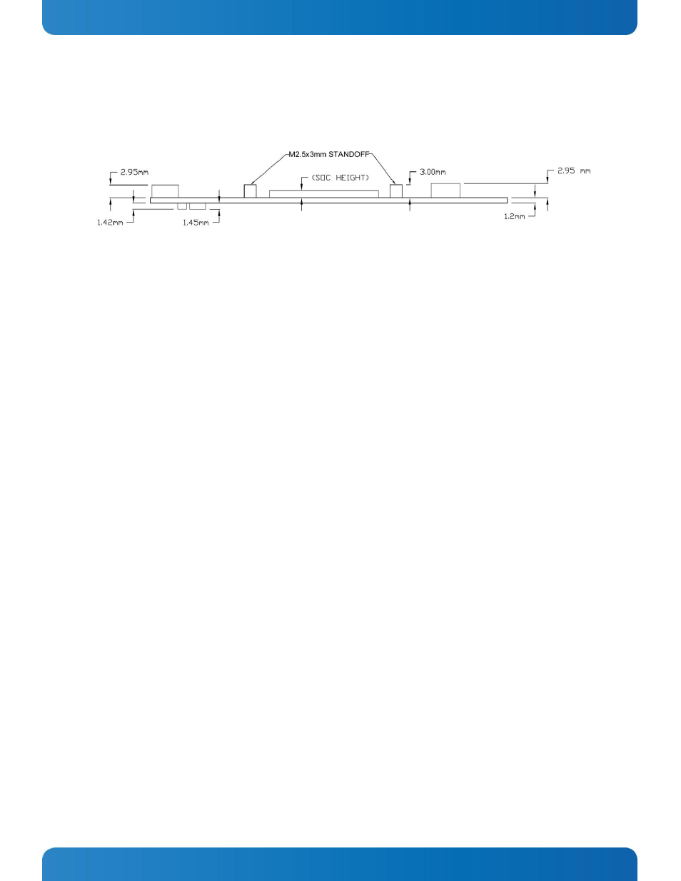
ULP-COM sA3874i height information is shown in Figure 10: ULP-COM sA3874i Edge View below:
Figure 10: ULP-COM sA3874i Edge View
The SOC height, above the PCB, based on measurements performed on a number of assembled units, is 2.7mm +/-
0.1mm.
3.4.5 Module Assembly Hardware
The ULP-COM sA3874i module is attached to the carrier with four M2.5 screws. A 4mm length screw is usually
used. The attachment holes are located on the corners of the module. Attachment holes have a 6mm diameter
pad, 2.7 mm dia drill hole as shown Figure 7: ULP-COM sSA3874I Top Side Components.
3.4.6 Module Cooling Solution Attachment
Two Penn Engineering and Manufacturing (PEM) “SMTSO” surface mount standoffs with M2.5 internal threads and
3mm stand-off height are soldered into the Module top side, adjacent to the TI Cortex A8 SoC. They are provided
for the attachment of a heat spreader or heat sink, independent of the corner mounting holes. The PEM SMTSO
parts have excellent pull- strength and the Module PCB will deform before the standoffs can be pulled out.
The heat sink/heat spreader mounting holes are shown in Figure 7: ULP-COM sSA3874I Top Side Components. The
Heat Spreader is secured to the Module with two 6mm flathead M2.5 screws.
For a large-area heat spreader or heat sink, the corner holes should be used as well, with suitable standoffs.