8 lpc bus interface, Lpc bus interface – Kontron COMe-cXLi2 User Manual
Page 44
Kontron COMe-cXLi2 User’s Guide
www.kontron.com
38
For cable lengths and terminations on your baseboard, refer to the PICMG COM
Express® Design Guide on the PICMG website.
Configuration
The Ethernet controller is a PCI Express bus device. The BIOS allocates the
required system resources during the configuration of the PCIe device.
4.2.8
LPC Bus Interface
The Low Pin Count (LPC) interface signals are connected to the LPC bus
bridge, which is located on the US15WPT system controller hub. The LPC low-
speed interface can be used for peripheral circuits. For example, it can be
used as an external super I/O controller to combine legacy-device support
into a single IC. The implementation of this subsystem complies with the COM
Express® specification. For additional implementation information, refer to
the PICMG COM Express® Design Guide on the PICMG website.
The LPC bus does not support DMA (Direct Memory Access) and therefore imposes
limitations for ISA bus and standard I/Os (SIOs) like floppy or LPT interface
implementations.
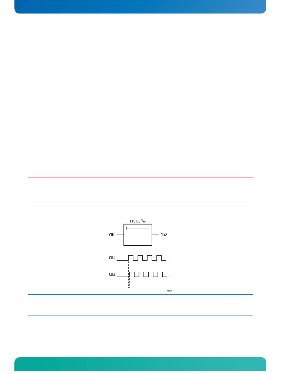
WARNING: When more than one device is connected to the LPC bus, a clock
buffer is required. Because of the power management of the LPC bus,
you must use great care with clock buffers that require
synchronization as they could prevent the board from booting up.
Figure 6: Standard Clock Buffer
NOTE: When using a standard clock buffer on the baseboard, be aware that the
generated delay must be considered for the length matching of the
layout.
Clock Buffer Reference Schematic