1 pin-outs, Pin-outs, Table 3: connector x1a - row a – Kontron COMe-cXLi2 User Manual
Page 21
Kontron COMe-cXLi2 User’s Guide
www.kontron.com
15
Type
Description
PWR
Power Connection
nc
Not connected, Signal not available
Note:
To protect external power lines of peripheral devices, make sure
that the wires have the right diameter to withstand the maximum
available current and the enclosure of the peripheral device fulfils
the fire-protection requirements in IEC/EN60950
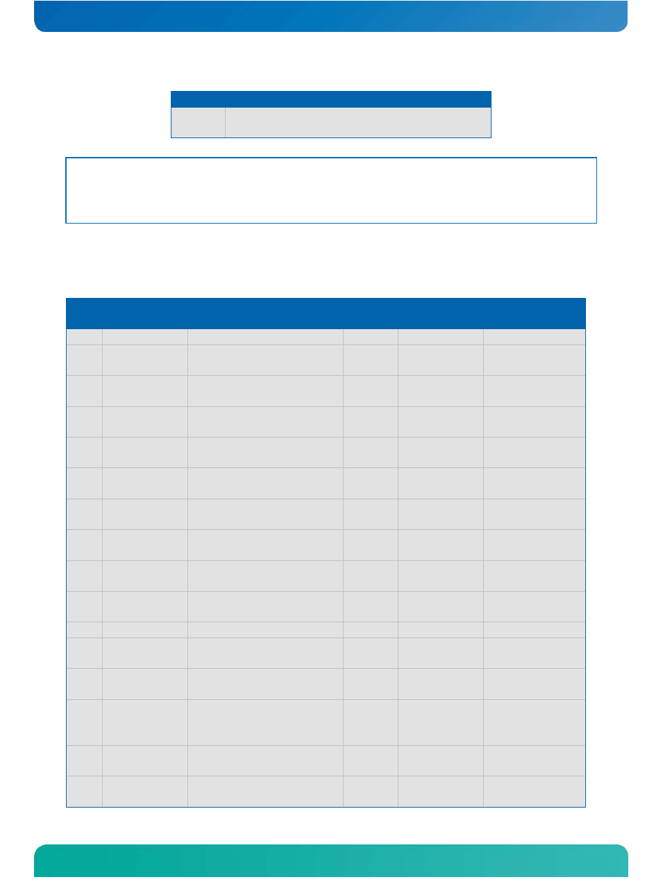
4.1
Pin-Outs
Table 3: Connector X1A - Row A
Pin
Signal
Description
Type
Terminatio
n
Comment
A1
GND_1
Power Ground
PWR
-
-
A2
GBE0_MDI3-
Ethernet Receive
Data-
DP-I
Intel
82574IT
-
A3
GBE0_MDI3+
Ethernet Receive
Data+
DP-I
Intel
82574IT
-
A4
GBE0_LINK100
#
Ethernet Speed LED
100Mbps
O-3.3
Intel
82574IT
-
A5
GBE0_LINK100
0#
Ethernet Speed LED
1000Mbps
O-3.3
Intel
82574IT
-
A6
GBE0_MDI2-
Ethernet Receive
Data-
DP-I
Intel
82574IT
-
A7
GBE0_MDI2+
Ethernet Receive
Data+
DP-I
Intel
82574IT
-
A8
GBE0_LINK#
LAN Link LED
OD
Intel
82574IT
-
A9
GBE0_MDI1-
Ethernet Receive
Data-
DP-I
Intel
82574IT
-
A10
GBE0_MDI1+
Ethernet Receive
Data+
DP-I
Intel
82574IT
-
A11
GND_2
Power Ground
PWR
-
-
A12
GBE0_MDI0-
Ethernet Transmit
Data-
DP-O
Intel
82574IT
-
A13
GBE0_MDI0+
Ethernet Transmit
Data+
DP-O
Intel
82574IT
-
A14
GBE0_CTREF
LAN Reference Voltage O-1.8
is on a
power rail
controlled
-
A15
SUS_S3#
Indicates Suspend to
RAM state
O-3.3
CPLD I/O
CPLD I/O
A16
SATA0_TX+
SATA 0 Transmit Data+ DP-O
Marvell
88SA8052A1
-