1 connector j1 – cpld debug, 2 connector j2 – so dimm ddr2 soldered, 3 connector j3 - us15wpt jtag connector – Kontron COMe-cXLi2 User Manual
Page 38: Connector j1 – cpld debug, Connector j2 – so dimm ddr2 soldered, Connector j3 - us15wpt jtag connector
Kontron COMe-cXLi2 User’s Guide
www.kontron.com
32
Note: The termination resistors in this table are already mounted on the COM
Express® board. Refer to the PICMG COM Express® Design Guide for
information about additional termination resistors.
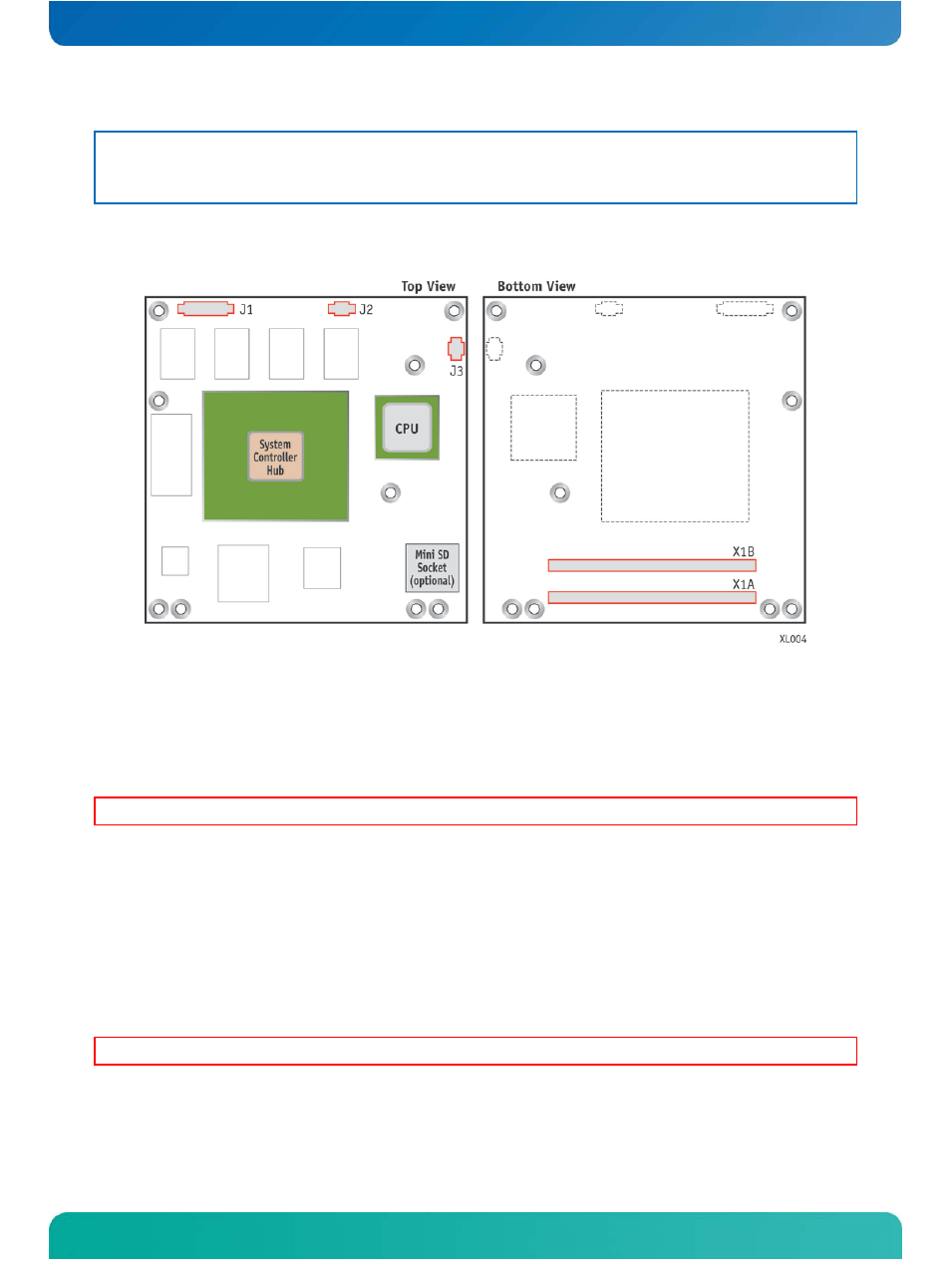
Figure 4: Onboard Connectors
J1 - CPLD Debug
4.1.1
Connector J1 – CPLD Debug
The onboard 12-pin connector J1 is for accessing the CPLD.
WARNING: The debug port is for internal use only. Do not connect any devices.
4.1.2
Connector J2 – SO DIMM DDR2 Soldered
There is up to 2 GBytes of DDR2 memory supplied on board.
4.1.3
Connector J3 - US15WPT JTAG Connector
This is the US15WPT debug connector
WARNING: The debug port is for internal use only. Do not connect any devices.
See also other documents in the category Kontron Hardware:
- CP3003-SA uEFI BIOS (72 pages)
- CP3003-SA (36 pages)
- CP3002 (38 pages)
- CP3002-RC uEFI (64 pages)
- CP-RIO3-05 (42 pages)
- CP3002-RC (30 pages)
- CP342 (52 pages)
- CP930 (46 pages)
- CP932 (52 pages)
- CP346 (72 pages)
- CP384 (66 pages)
- CP383 (74 pages)
- CP382 (58 pages)
- CP381 (60 pages)
- CP372 (64 pages)
- CP371 (60 pages)
- CP-RIO3-04S (38 pages)
- CP390 (36 pages)
- CPS3410 (9 pages)
- CPS3402 (9 pages)
- CPS3105 (9 pages)
- CPS3101 (9 pages)
- CPS3003-SA (19 pages)
- PB-SIO4 (34 pages)
- PB-SIO4A (34 pages)
- PB-DOUT8 (34 pages)
- VMOD-2 (82 pages)
- VSBC-32 (110 pages)
- VM42 (62 pages)
- Bootstrap Loader (24 pages)
- VMP1 with Netbootloader (120 pages)
- VMP1 (106 pages)
- NetBootLoader (86 pages)
- VMP2 (142 pages)
- VMP3 (154 pages)
- CP-RIO6-923 (32 pages)
- CP-RIO6-923-F (32 pages)
- CP-RIO6-001 (28 pages)
- CP-RIO6-001-HD-VGA (46 pages)
- CP-RIO6-M (20 pages)
- CP-RIO6-B (28 pages)
- CP6925 (42 pages)
- CP6002 uEFI BIOS (76 pages)
- CP6002 IPMI (40 pages)
- CP6002 (42 pages)