Elecraft XV Assembly Manual for XV432 MHz User Manual
Page 7
- 5 -
Preventing Electrostatic Discharge Damage
Your XV transverter uses integrated circuits and transistors that can be
damaged by electrostatic discharge (ESD). Problems caused by ESD can
be difficult to troubleshoot because components may be degraded but still
operating, rather than fail completely.
To avoid such problems, simply touch an unpainted, grounded metal
surface before handling any such components and occasionally as you
build, especially after moving about.
For maximum protection, we recommend you take the following anti-
static precautions (listed in order of importance):
1. Leave ESD-sensitive parts in their antistatic packaging until you
install them. The packaging may be a special bag, other container
or the leads may be inserted in conductive foam (Figure 2). Parts
which are especially ESD-sensitive are identified in the parts list.
2. Touch an unpainted metal ground before handling any sensitive
parts or wear a conductive wrist strap with a series 1 megohm
resistor. DO NOT attach yourself directly to a ground as this
poses a serious shock hazard.
3. Make sure your soldering iron has a grounded tip.
4. Use an antistatic mat on your work bench.
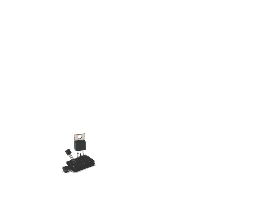
Figure 2. A common antistatic packaging is conductive foam which
keeps all of the terminals of a device at the same potential.
Unpacking and Inventory
We strongly recommend that you do an inventory of the parts before
beginning to assemble the kit. Even if you don’t count all the parts, an
inventory is helpful to familiarize yourself with them. A complete parts
list is included in the next section.
Identifying Parts
The parts list contains illustrations of the parts to help you identify them.
Identifying marks on the individual parts are shown in the text in
parenthesis. For example, “Transistor Q4 (PN2222)…” indicates a
transistor, Q4, which may be located in the parts list that has the
characters shown in parenthesis printed on it. Sometimes these letters are
not obvious. For example, they may be printed in light gray on a black
body. Also, there may be other marks on the device in addition to the
letters listed.
Identifying Resistors
Resistors are identified by their power capacity and their resistance value.
The power rating in watts determines the physical size of a resistor. The
most common resistors are 1/4 watt. Higher wattage resistors are
proportionately larger. The resistance value and wattage of each resistor
is shown in the Parts Lists and in the individual steps of the assembly
procedures. The silk-screened outlines on the PCBs indicate the relative
physical size of the resistors as well.
Most resistors use a color code. The color bands are listed in the text
along with the values of each resistor. For example, “R4, 100k (brn-blk-
yel)…” indicates a 100k ohm resistor and the colors to look for are
brown, black and yellow, starting with the band nearest the end of the
resistor.
Some resistors use numbers instead of color bands. For example, an 820
ohm resistor might be stamped with the digits 821 instead of having gray,
red and brown color bands. Some larger resistors have their value in
ohms stamped on the body using numbers. For, example the 820 ohm
resistor would be stamped with 820 instead of 821 as described above.
Normally, when the value is shown in ohms it will be followed with the
word “ohms” or the Greek letter omega: Ω