Elecraft XV Assembly Manual for XV432 MHz User Manual
Page 39
- 37 -
Solder the two ground lugs on antenna connector J1 to the PCB (See
Figure 33).
SOLDER
WIRE TO
CENTER
TERMINAL
SOLDER GROUND
LUGS TO PCB
PADS. (2 PLACES)
Figure 33. Antenna Connection J1 Installation.
Bend the 16 gauge wire you previously soldered in the PCB antenna
pad so that it rests against the antenna connector center terminal, then
solder. Keep this lead as short as possible as shown in Figure 33. Trim off
excess wire.
Strip the insulation from a 2” (5 cm) length of the #24 hookup wire.
Wrap the wire around the alignment tool twice as shown in Figure 34
to form a two-turn self-supporting coil. Use the thicker portion at the end
of the alignment tool with the hex driver exactly as shown, not the larger
end with the screwdriver tip. Instead of the alignment tool, you can use
the shaft of an 9/64-inch (or 3.5 mm) drill bit.
WRAP WIRE AROUND SHAFT
ON THE END WITH THE HEX
DRIVER.
DO NOT USE LARGER END
WITH SCREWDRIVER TIP.
Figure 34. Winding L10 on the Alignment Tool.
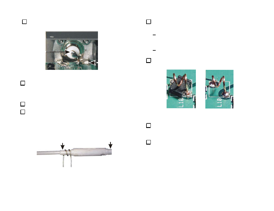
Position the coil in the pads for L10 in the upper left quadrant as
shown in Figure 35.
Adjust the coil so the turns are even and the wires go straight
down into the pads on the PCB as shown. The spacing of the
pads defines the correct length of the coil.
Use a jumper shorting block laying on its side to set the
correct height of the coil above the PCB.
Solder the coil in place. Remove the shorting block from under
L10 and clip the leads as short as possible on the bottom of the PCB.
READY TO SOLDER
FINISHED
Figure 35. Installing L10.
Position relay K10 (G6B-1174P) in the upper left quadrant near
antenna connector J1. Hold it in place and tack-solder pins at opposite
corners.
Check to ensure the relay is against the PCB. If necessary, reheat
the corner pins while pressing down on the relay. When it is properly
positioned, solder all four pins. Do not trim the pins.