Elecraft XV Assembly Manual for XV432 MHz User Manual
Page 42
- 40 -
i
In the following steps you will install the hardware that
attaches the RF power module to the bottom cover. Follow the steps
carefully to ensure the module makes good thermal contact with the
bottom cover and the leads line up properly with the RF PCB. The
completed hardware assembly is shown in Figure 42.
On the inside surface of the bottom cover find the four holes along
one side that match the holes in the heat spreader. They are between the
two groups of cooling holes in the cover.
Test-fit the larger of the two thermal conduction pads so that the
holes in the pad line up with the holes in the cover. Orient the pad so it
does not hang over the edge of the bottom cover.
Lift the thermal conduction pad and clean the surface of the bottom
cover under the pad using sandpaper, a sharp knife or other tool if needed.
The thermal conduction pad must rest against clean metal.
Clean the paint off of the inside surface of the bottom cover around
the screw holes in the four corners where the 2-D fasteners will attach it
to the RF PCB.
Inspect the edges of the heat spreader and remove any burrs with the
edge of a flat-blade screwdriver, knife or small file. Note that two of the
holes in the heat spreader are tapped and two are not.
Replace the larger of the two thermal conduction pads over the clean
metal area on the inside of the bottom cover so that the holes in the pad
line up with the holes in the cover. Be sure the pad does not hang over the
edge of the bottom cover.
Place the heat spreader on the thermal conduction pad so the screw
holes line up. The unthreaded holes should be closest to the edge of the
bottom cover. Put a 1/2” (12.7 mm) pan head screw through each
unthreaded hole with the head on the bottom cover. Place a nut on each
screw and finger tighten to hold them temporarily.
Insert two black 3/16” (4.8 mm) pan head screws through the
bottom cover into the threaded holes in the heat spreader. Tighten the
screws.
Lay the bottom cover on a clean, smooth surface with the heat
spreader facing up.
Remove the nuts from the long screws but do not remove the
screws. If you have installed feet on the bottom cover, place a small
book that fits between the feet under the cover so the long screws do
not fall out.
Place the smaller thermal conduction pad over the screws. Orient
the pad so it does not hang over the edge of the heat spreader. If the
pad is too large no matter which way your orient it, use a sharp knife
or scissors to trim it. When the RF power module is installed it must fit
as shown in Figure 39.
i
Observe the ESD precautions on page 5 before handling
the RF power module.
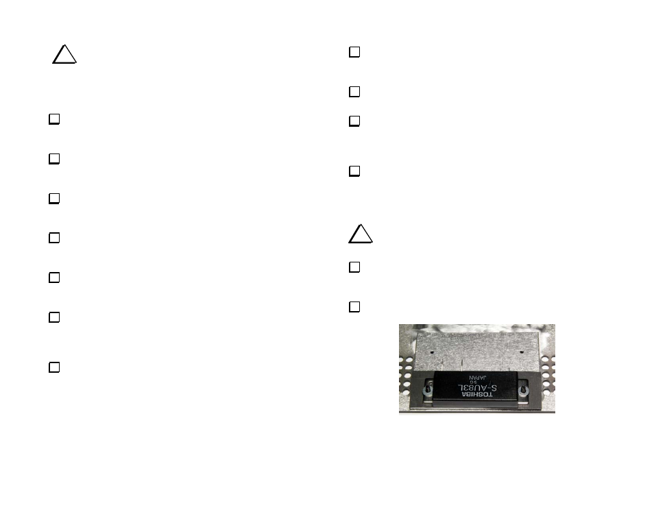
Position the RF power module on the two screws as shown in
Figure 39. Be sure the thermal conduction pad on the heat spreader is
resting directly against the bottom of the RF power module.
Place a flat washer on each screw as shown in Figure 39.
Figure 39. RF Power Module and Flat Washers in Place on the
Heat Spreader.