Elecraft XV Assembly Manual for XV432 MHz User Manual
Page 35
- 33 -
i
The following transistor is particularly sensitive to
electrostatic discharge (ESD) damage. Take ESD precautions (see
page 5). Wear a grounded antistatic wrist strap or, as a minimum,
touch an unpainted, grounded object before handling Q5.
Install transistor Q5 (2N7000) in the lower right quadrant (at the right
edge of the PCB).
Install two 2-pin header connectors next to Q5.
__JP8 __JP7
i
In the following steps you will install two very similar voltage
regulators. Be sure to read the numbers and install the correct part in
each location.
Install voltage regulator U2 (78L09) in the lower right quadrant of
the PCB.
Install voltage regulator U3 (78L05) near the center of the PCB.
i
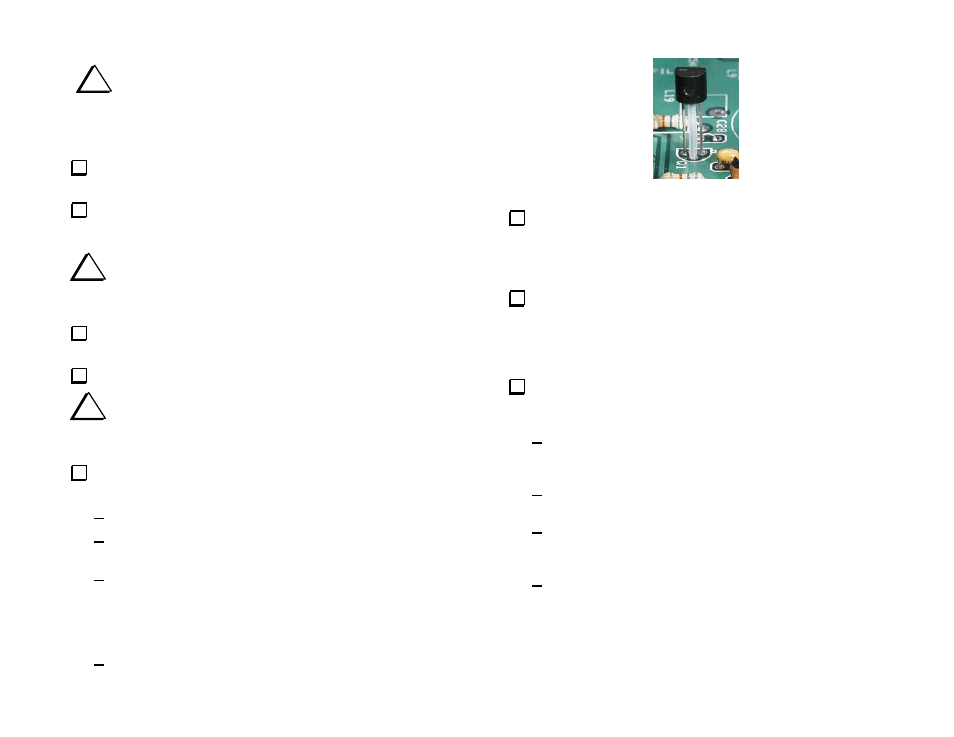
Read the following step completely and refer to Figure 23
before installing Q1. Q1 is installed differently from other transistors
in this kit.
Install transistor Q1 (NTE108) in the upper right quadrant near the
circle for OV1 as follows:
Locate the Teflon tubing and cut it to a length of 3/8” (8 mm).
Slide the 3/8” (8mm) length of Teflon tubing over the center lead
of transistor. It must touch the body of Q1.
Position Q1 so that the Teflon tubing acts as a spacer to hold the
transistor above the PCB (see Figure 23). One end of the tubing
should contact the bottom of Q1’s case and the other end should
rest against the top of the PCB. Spread the leads on the bottom of
the PCB to hold Q1 in place.
On the bottom, solder and trim the leads as short as possible.
Figure 23. Installing Q1 with Teflon Spacer.
Install the DPDT power switch at SW2 in the lower right corner
of the PCB. Orient the switch so the pushbutton shaft extends out over
the edge of the PCB. Be sure the two feet on the bottom of the switch
are resting against the PCB before soldering.
Install crystal Y1 within the rectangular outline inside the circle
for OV1 in the upper right quadrant. The crystal may be oriented either
way. Be sure the crystal case is sitting directly against the PCB. Do
not hold your soldering iron on the leads more than 2 or 3 seconds
maximum. Excessive heat may damage the crystal.
If you purchased the optional crystal oven with your transverter
(Elecraft part number E980076) install it now as follows:
Position the oven down over the crystal so the three leads on
the oven pass through the +, - and NC holes in the PCB. The
oven will only go on the crystal one way.
Bend the leads over on the bottom of the RF PCB to hold the
oven in place, then tack-solder one lead.
Check to be sure the oven fully seated down over the crystal
and against the PCB. If necessary, reheat the soldered lead
and adjust its position.
Solder and trim all three leads.