Elecraft XV Assembly Manual for XV432 MHz User Manual
Page 24
- 22 -
i
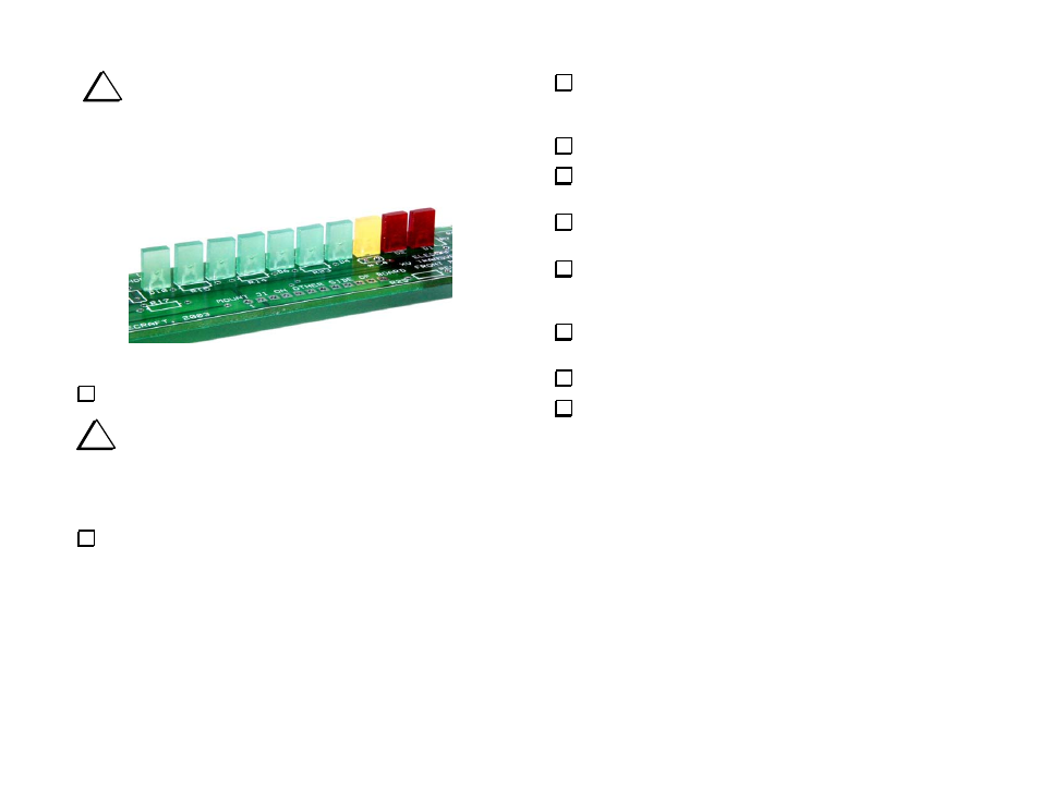
The remaining parts will be installed on the front of the PCB.
Follow the LED installation instructions carefully to preserve the
appearance of your transverter’s front panel. When finished, the
LEDs should be perpendicular to the PCB and in a straight line (See
Figure 11).
Figure 11. Power LEDs Installed on Front Panel PCB.
Sort the rectangular LEDs into groups according to color.
i
Note that one lead of each LED is longer than the other. This
is the anode lead. It must be inserted in the right hand solder pad for
each LED as shown on the front panel PCB. The right hand pads are
square to help identify them. The LEDs will not illuminate if the leads
are reversed.
Insert the leads of a green LED through the solder pads provided for
D10 on the silk-screened side of the front panel PCB. Be sure the long
lead is in the right-hand pad (with the square pad). Do not solder yet.
Hold the LED with the back of the plastic housing flat against the
PCB (not tilted). Bend the leads outward on the bottom side to hold it
in place.
Solder one lead of the LED, keeping soldering time to 1 to 2 sec.
If the LED is tilted or is not flat against the PCB, reheat the lead
while pressing the LED down.
Once the LED is correctly positioned, solder the other lead, again
keeping soldering time to 1 or 2 seconds. Then trim both leads.
Install a green LED at D9. Make sure the long lead is to the
right as shown on the PCB. Before soldering, adjust the LED's
position as with D10.
Install green LEDs at D8, D7, D6, D5, and D4. Make sure the
long lead is to the right for these and all remaining LEDs.
Install a yellow LED at D3.
Install red LEDs at D2 and D1.