Elecraft XV Assembly Manual for XV432 MHz User Manual
Page 32
- 30 -
Install PC trimmer potentiometer R39, 1 K-ohm (102) near the
center of the PCB as you did R10 and R22.
Locate the 25-ohm PC board trimmer potentiometer R13. This
potentiometer may not show a value. Confirm the value with your DMM.
The value your DMM reports may not be exactly 25 ohms.
i
After removing the temporary jumper in the following step,
amplifier Q3 will be exceptionally vulnerable to ESD damage until
R13 is in place. Take ESD precautions (see page 5) when handling.
Remove the temporary jumper from the pads for R13 in the upper left
quadrant of the PCB near D3 and install the 25-ohm trimmer
potentiometer R13. This trimmer will sit down against the PCB.
Install 4-pole DIP switch SW1 in the space provided in the lower left
quadrant of the PCB. The DIP switch may not have a notch at one end to
line up with the silk-screened outline. Orient the switch so that the ON
positions are on the side with the silk-screened numbers. If you aren’t
sure, use your DMM to check the orientation of the switch assembly so
there is continuity through each switch when the toggle is toward the silk-
screened number on the circuit PCB.
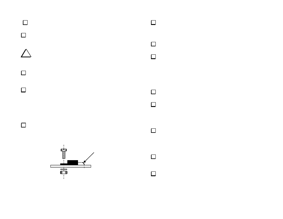
Bend the leads of voltage regulator U4 (78M05C) to fit in the space
provided in the lower left quadrant of the PCB as shown in Figure 19.
Bend the leads around the shaft of a small screwdriver to create smooth
bends. Avoid making sharp bends in the leads.
USE SMOOTH BEND
Figure 19. Installing Voltage Regulator U4.
Insert U4’s leads into the holes. Secure it with a zinc or stainless
steel 4-40 x 5/16” (8 mm) screw, #4 internal-tooth lock washer and 4-
40 nut as shown. The metal tab on the transistor should rest directly
against the metal foil on the circuit PCB.
Solder all three leads to U4 on the bottom side of the PCB and
trim them short.
Install two 22
F, 25 VDC electrolytic capacitors near the notch
on the left side of the PCB. Be sure to observe polarity. The longer
positive lead goes in the square solder pad with a
+
silk-screened
next to it.
__C26
__C60
Locate diodes D10 and D11. They are square, red LEDs identical
to the ones you installed on the front panel PCB.
Locate the positions for D10 and D11 on the PCB, near the circle
for OV1 in the upper right quadrant. Note that the square solder pad
for D10 is to the left and the square solder pad for D11 is to the right.
The diodes must be installed turned 180 degrees with respect to each
other.
Position diode D10 on the PCB with the long lead through the
square pad on the left and the short lead through the round pad.
Position the body of the LED directly against the PCB within the silk
screen outline and spread the leads under the PCB to hold the diode in
place.
Solder one lead on the bottom of the PCB. Check to be sure the
LED is still positioned directly against the PCB. Reheat and adjust the
LED as necessary, then solder and trim both leads.
Position diode D11 on the PCB with the long lead through the
square pad on the right, opposite the orientation of D10. Solder and
trim the leads as you did for D10.