Elecraft XV Assembly Manual for XV432 MHz User Manual
Page 46
- 44 -
Press the key cap onto the On/Off switch shaft until it clicks in
place.
Attach a 2-D fastener to the each screw hole at the top corners of the
front and rear chassis end panels with 3/16” (4.8 mm) screws. Be sure the
widest side of each 2-D fastener is facing so the edge lines up flush with
the edge of the panel as shown in Figure 46.
Figure 46. Attaching 2-D Fasteners to Cabinet End Covers.
Attach the side panels using four 3/16” (4.8 mm) screws in each
panel. You may need to loosen the other screws temporarily to line up the
screw holes properly.
i
In the following step be sure to orient the Anderson power
connector shells exactly as shown. Otherwise, the connector will not
mate with the connector on the transverter.
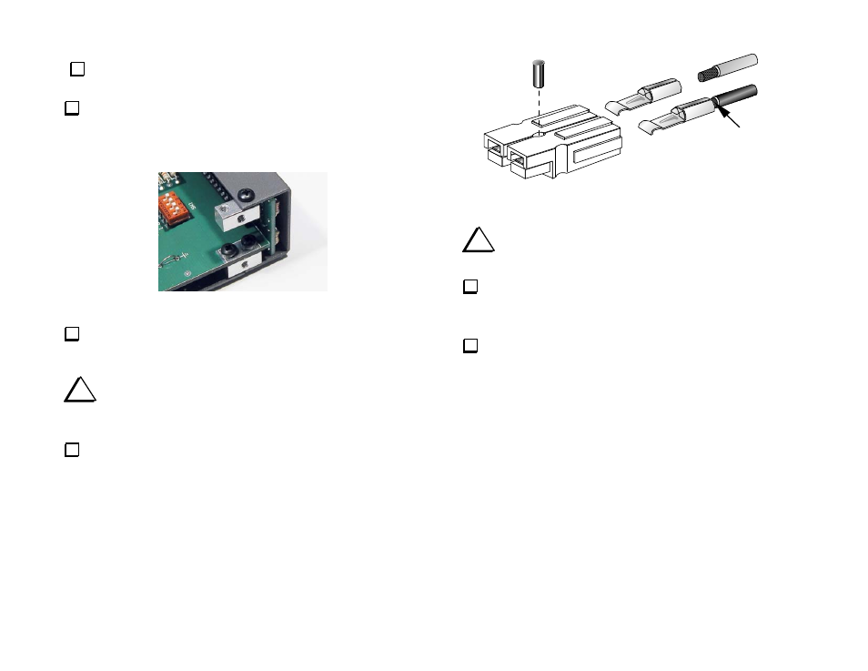
Locate the two Anderson power connector shells. Orient them as
shown in Figure 47 and slide them together so the tongue on one side
fully engages the groove on the other half.
BLACK
RED
SOLDER
Figure 47. Power Cable Connector Assembly.
i
Use only the supplied 12 AWG, 2-conductor stranded wire
(red/black) for the DC power cable.
Separate the two conductors at one end of the 12 AWG, 2-
conductor cable. Remove 5/16” (8 mm) of insulation from the red and
black wires at one end. Do not nick or cut off any of the strands.
Insert the wires into the terminals as shown above. Solder the
wires to the crimp terminals, using enough solder to completely
surround the wire and fill the interior of the terminal. (This may take
as long as 10 seconds if you’re using a small iron.) Be careful not to
get solder on the tongue that extends from the front of the terminal.