Elecraft XV Assembly Manual for XV432 MHz User Manual
Page 13
- 11 -
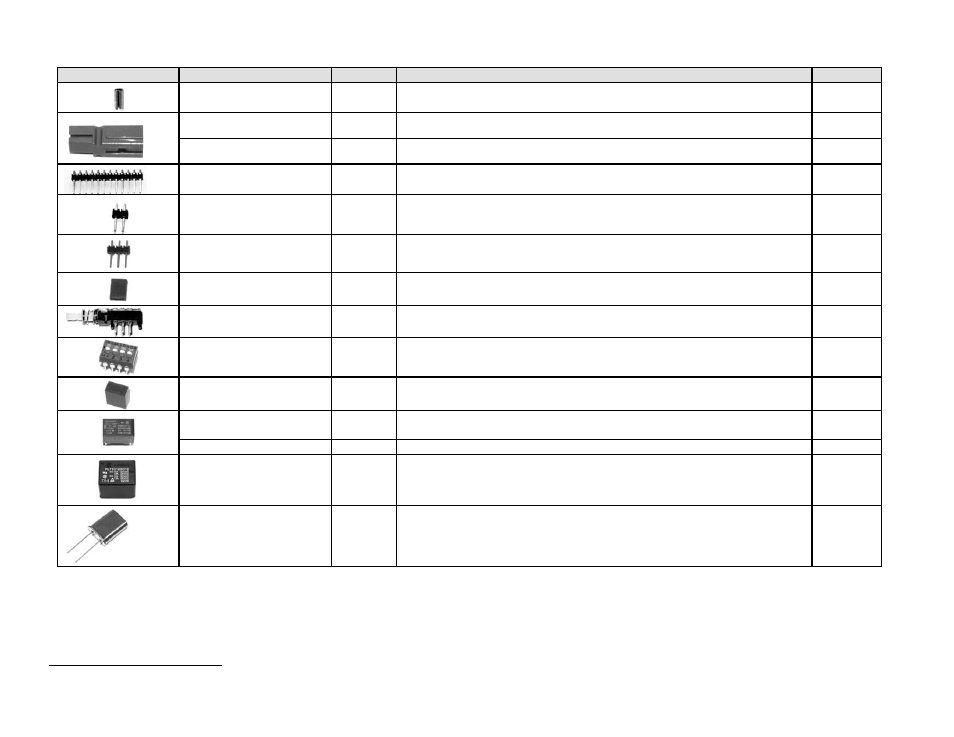
Picture
Ref. Designator(s)
QTY
Description
Part #
1
Anderson Powerpole® Connector Roll Pin
E700071
J7 & mating cable plug
2
Anderson Powerpole® Shell, Red
E620059
J7 & mating cable plug
2
Anderson Powerpole® Shell, Black
E620060
P1
1
Header Connector, 12 Pin , Right Angle
E620065
JP9
2
,JP7, JP8
3
Header Connector, 2 Pin
E620054
JP1,JP2,JP3,JP4, JP5,
JP6, JP9
2
7
Header Connector, 3 Pin
E620007
9
Header Shorting Block, 2 Pin
E620055
S2
1
DPDT Power switch
E640006
SW1
1
4 Pole DIP switch
E640014
1
Key Cap, Black
E980023
K1, K2, K4, K5, K6, K7,
K8, K9
8
Relay
(
G6E-134P
)
E640011
K10 1
Relay
(G6B-1174P)
E640028
K3
1
Relay, SPDT, 12 A, 12 VDC, Large (KLT1C12DC12).
E640012
Y1
1
Crystal, 134.667 MHz 5th Overtone HC43/U
E660045
2
JP9 comprises a three pin and a two pin header connector.
- KX3 Owner's Manual (58 pages)
- KX3 Assembly Manual (47 pages)
- KX3 Assembly Manual Errata (5 pages)
- KX3-2M (30 pages)
- KX3-PCKT (2 pages)
- KX3 Mobile Installation And Operation Guide (17 pages)
- KX3 Guide for Blind Operators (7 pages)
- KX3 Quick Reference (2 pages)
- K3 Programmers Reference (26 pages)
- KX3 Speaker Grille Instructions (9 pages)
- KXFL3 Filter Option (12 pages)
- KXFL3 Filter Option Errata (2 pages)
- KXAT3 (5 pages)
- KXBC3 (13 pages)
- KXPD3 (4 pages)
- Proset Boom Headset (1 page)
- PX3 Owner's Manual (53 pages)
- PX3 Owners Manual Errata (2 pages)
- KXPA100 Manual (55 pages)
- KXPA100 Assembly Manual (27 pages)
- KXPA100 Assembly Errata (1 page)
- KXPA100 Programmers Reference (24 pages)
- KXAT100 Installation Manual (17 pages)
- KX1 Manual (96 pages)
- KXAT1 (12 pages)
- KXPD1 (7 pages)
- KXB30 (8 pages)
- KXB3080 (20 pages)
- K1 (91 pages)
- K1 1.09 F/W (1 page)
- KNB1 Manual (8 pages)
- KAT1 Manual (15 pages)
- KFL1-2 (2 pages)
- KTS1 (1 page)
- KBT1 Manual (8 pages)
- KBT1 Manual Errata (2 pages)
- K1BKLTKT LCD Mod Kit (6 pages)
- K2 Owner's Manual (171 pages)
- K2 Owner's Manual Errata (1 page)
- K2 PLL (4 pages)
- K2ATOBKIT (15 pages)
- K2ATOBKT (2 pages)
- K2 Keying Modification Instructions (4 pages)
- KPA100 Manual (74 pages)
- KPA100 Shield Upgrade (3 pages)