Elecraft XV Assembly Manual for XV432 MHz User Manual
Page 40
- 38 -
i
In the following steps, you’ll choose whether to set up your
transverter for use with a single antenna and feed line or for use with
separate transmitting and receiving antennas and separate feed lines.
Do only one of following two steps.
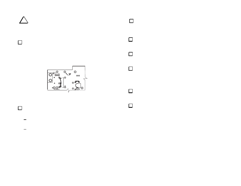
Antenna Option 1: If you are building your transverter for use with
separate (split path) transmit and receive antenna connections and
separate feed lines, use discarded leads to form jumpers across W2 and
W3 in the upper left quadrant as shown in Figure 36. Solder the jumpers
on the bottom side of the PCB to avoid touching the relay or trimmer C1
with your iron.
J1
C44
K1
W3
K10
W2
J8
C1
C42
Figure 36. Installing W2 and W3 for Split Path (Separate Transmit
and Receive Antenna) Operation. Do Not Install Relay K1.
Antenna Option 2: If you are building your transverter for use with
a single antenna used for both transmit and receive, do the following:
Verify that jumpers W2 and W3 are not installed in the spaces
shown in Figure 36 (above).
Install the remaining relay K1 (G6E-134P) directly behind the
antenna connector. Use the same technique described for relay
K10. Do not trim the leads after soldering.
Locate the cooling fan. Inspect the sides of the fan and find the
two arrows molded into the plastic. One identifies the direction of fan
rotation and the other indicates the direction of airflow when the fan is
operating.
Position the fan over the outline at the center of the PCB so the
air will flow up and away from the PCB. The wires should exit the fan
housing nearest the lower right quadrant of the PCB (see Figure 37).
Attach the fan to the PCB using four 5/8” 4-40 pan head screws
inserted from the top and secured with 4-40 inside tooth lock washers
and nuts on the bottom of the PCB.
Separate the two conductors of the fan lead. They will pull apart
into separate insulated wires once the web of insulation is cut between
them at the end. Take care to start the cut in the center so that pulling
them apart doesn’t expose one of the conductors along its length. Pull
the wires apart to a point about 1” (2.5 cm) from the fan housing.
Cut and strip the wire with a black stripe to fit in solder pad B
near the corner of the fan. Be sure you place the wire in solder pad B.
Solder pad A nearby is not used.
Route the red wire alongside relay K6 and then pass the through
the hole in the circuit via to the bottom of the PCB as shown in Figure
37. Pull all the wire through the via and position the lead as shown.