Dynojet 424xLC2: Installation Guide User Manual
Page 90
C H A P T E R 3
Deck Installation
Above Ground Model 424x/424xLC
2
Automotive Dynamometer Installation Guide
3-48
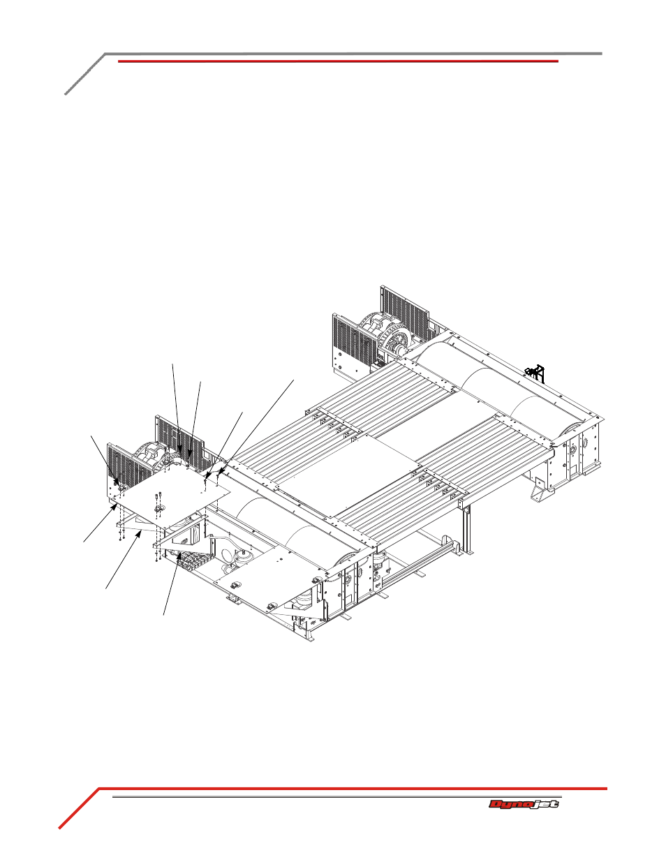
8
Install the outside panels.
8a
Secure the panel to the dyno frame using the 3/8-16 x 1.5-inch button-head
flange bolt removed in step #7 and two additional 3/8-16 x 1.5-inch button-
head flange bolts.
8b
Secure the three tie downs to the panel and to the deck braces using two 3/8-
16 x 1.5-inch flange hex bolts, two 3/8-inch washers, and two 3/8-inch
nylock nuts each.
Verify the panel is sandwiched between the tie-downs and the brace.
8c
Secure the inside of the panel to the inner brace using one 3/8-16 x 1.5-inch
flange hex bolt, one 3/8-inch washer, and one 3/8-inch nylock nut.
8d
Tighten the bolts securing the braces to the dyno frame.
Figure 3-33: Install the Outside Panels
A 621
D
panel
tie-down
inside bolt
step 8c
outer brace
inner brace
reserved bolt
step 8a
step 8a
step 8a