Dynojet 424xLC2: Installation Guide User Manual
Page 116
C H A P T E R 4
Load Cell Calibration
Above Ground Model 424x/424xLC
2
Automotive Dynamometer Installation Guide
4-20
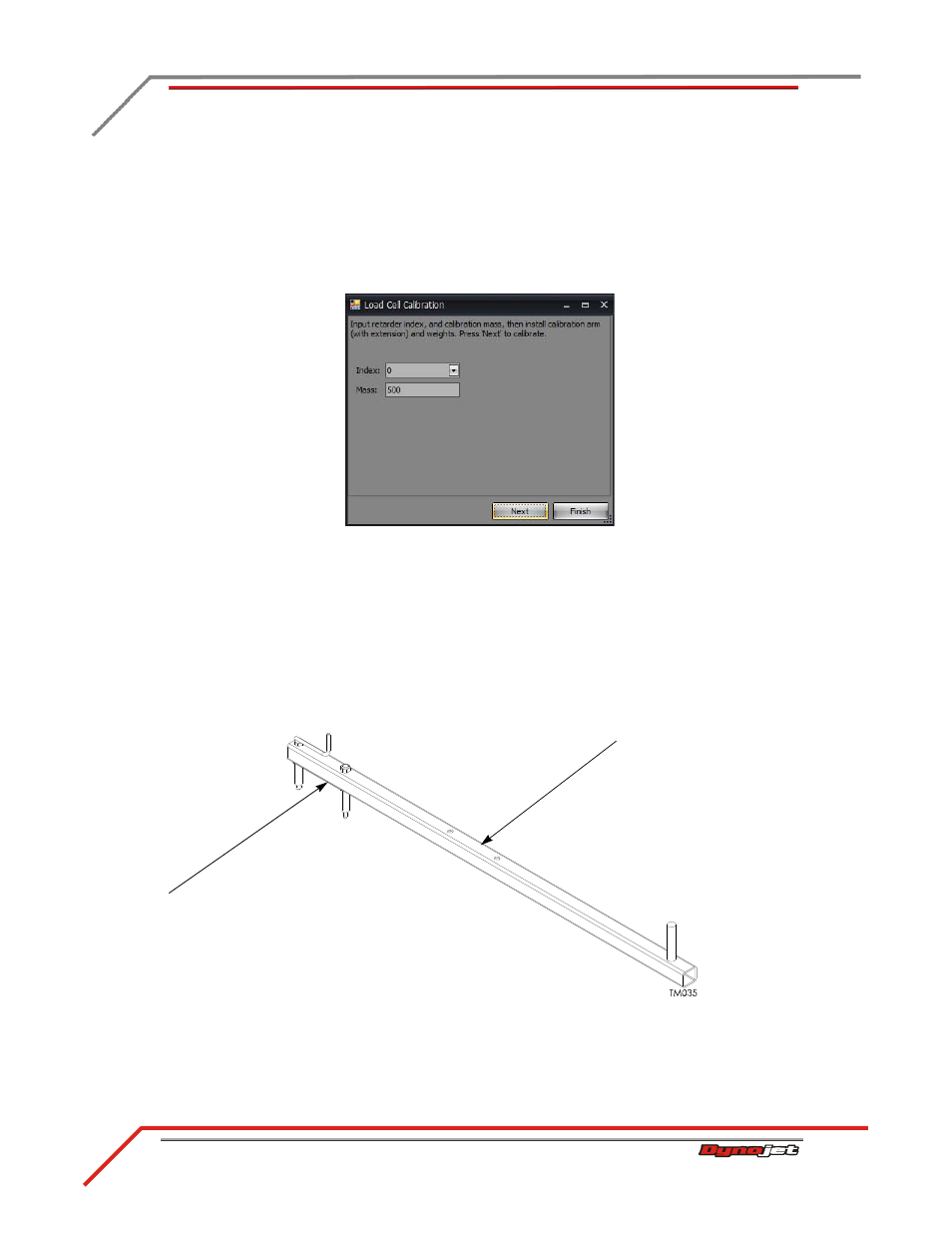
Once the load cell is zeroed, the Calibration Mass window will appear.
7
Enter the calibration arm value in the Mass box. Refer to Figure 4-21.
Note: You must perform this step the first time you calibrate the load cell.
Or
If you are only performing a Zero Calibration, click Finish.
Figure 4-20: Calibration Mass Window
Enter the calibration number stamped near the bolt pattern at the end of the
calibration arm in the Mass box. If you do not have enough room to use the bolt
pattern closest to the end of the calibration arm, use the number stamped near the
bolt pattern in the center of the arm.
Note: Dynojet recommends you secure the calibration arm using the bolt pattern
closest to the end of the arm unless space constraints in your dyno room do not
allow you to.
Figure 4-21: Calibration Arm Number
bolt pattern closest to
the end of the
calibration arm
bolt pattern near the
center of the
calibration arm