Dynojet 424xLC2: Installation Guide User Manual
Page 108
C H A P T E R 4
Eddy Current Brake Installation
Above Ground Model 424x/424xLC
2
Automotive Dynamometer Installation Guide
4-12
2
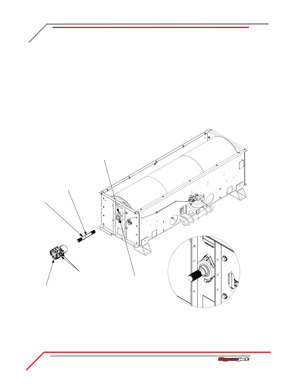
Insert the splined shaft through the bearing and into the spline hub of drum.
Note: Make sure the short splined end faces out.
3
Push the splined shaft in until the shoulder is flush with the bearing.
4
Torque the bearing mounting bolts to 57 foot-pounds.
5
Torque the two set screws on the bearing to 25 foot-pounds.
6
Remove the four bolts securing the u-joint to the keyed driveline yoke. Set these
bolts aside; they will be used to secure the eddy current brake to the driveline
assembly.
7
Separate the keyed yoke from the driveline assembly. You may need to use a
screwdriver or pry bar to separate the u-joint from the yoke.
8
Place the driveline assembly on the splined shaft.
Figure 4-10: Install the Splined Shaft and Driveline Assembly
EB244
driveline assembly
splined shaft
bearing set screws
bearing mounting
bolts
remove four bolts,
two on either side
shoulder