Dynojet 424xLC2: Installation Guide User Manual
Page 89
3-47
4 W D D Y N O I N S T A L L A T I O N
Deck Installation
Version 1
Above Ground Model 424x/424xLC
2
Automotive Dynamometer Installation Guide
4
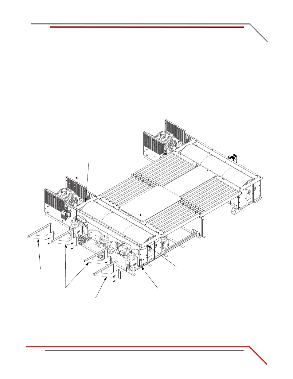
Loosely install the inner deck braces to the dyno using two 3/8-16 x 1.5-inch
flange hex bolts each.
5
Loosely install one outer deck brace to the eddy current brake using two
3/8-16 x 1.5-inch flange hex bolts, washers, and nuts.
6
Loosely install one outer deck brace to the mounting bracket using two
3/8-16 x 1.5-inch flange hex bolts, washers, and nuts.
Note: If you do not have an eddy current brake, the outer deck brace will secure
to a mounting bracket.
7
Remove one 3/8-16 x 1.25-inch button-head flange bolt from the left and right
drum guards.
Figure 3-32: Install the Deck Braces
A 620
D
mounting bracket
outer brace
inner brace
outer brace
right drum guard
left drum guard